

Why Are Large-Diameter Butterfly Valves Preferred for Hydro Turbine Inlet Applications?
2026-11-17
Why Does a Large Bore Matter at a Hydropower Turbine Inlet?
A large-diameter Butterfly Valve is often selected for a hydro turbine inlet because the penstock must deliver a substantial volume of water while keeping head loss, operating loads and maintenance demands within the project limits. At this point in the waterway, the valve is not simply a shut-off fitting. It is a major isolation and protection component positioned between the pressure conveyance system and the turbine. Its bore, disc profile, flow passage and actuator arrangement all influence how reliably the unit can be isolated during start-up, shutdown, inspection or an emergency trip.
As turbine output and unit flow increase, the inlet pipe diameter generally increases as well. A large-diameter Butterfly Valve sized to match the penstock can provide a full-bore flow path when fully open and avoid an unnecessary reduction in the waterway cross-section. This matters because even a modest local loss can translate into a meaningful power penalty in a high-flow installation. The actual loss, however, depends on the valve geometry, disc position, approach flow, reducer arrangement and system layout. Engineers should compare certified or calculated loss data rather than assume that nominal diameter alone guarantees low resistance.
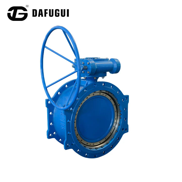
A large-diameter Butterfly Valve also makes handling, support and actuation more demanding. The valve body, disc, shaft, bearings, flange joints and foundation must withstand the operating pressure, transient loads and dead weight of the assembly. For this reason, Dafugui Pipe Valve Co., Ltd. offers a hydraulic control check design specifically identified for hydropower turbine inlets. The design combines shut-off, non-return and controlled-closing functions, helping the plant coordinate valve operation with turbine and penstock protection requirements.
How Does the Hydraulic Control Check Design Protect the Waterway?
A hydro turbine inlet Butterfly Valve normally operates as an isolation device rather than as a continuously modulating flow-control valve. During normal generation, it is generally held fully open. When the unit is taken out of service, the valve closes according to a sequence established by the hydraulic transient study and the plant control philosophy. The key engineering challenge is to stop or isolate the water flow without creating an unacceptable pressure surge in the penstock.
The hydraulic control check arrangement uses stored hydraulic energy to open the main valve and counterweight potential energy to drive closure. When the oil pump runs, pressurised oil acts on the hydraulic cylinder. The piston and lever lift the counterweight, moving the disc towards the open position. Once the valve reaches its required position, the hydraulic system maintains pressure through an accumulator. The manufacturer lists an accumulator pressure range of 20 to 32 MPa for this product. The actual set points and actuator sizing must be confirmed against the project design and the supplied actuator documentation.
During a planned turbine start, a bypass line can first equalise pressure across the main valve. The main valve can then open after the pressure difference has been reduced, allowing the turbine start sequence to proceed under controlled conditions. This is particularly important on large penstocks, where attempting to open against a substantial differential pressure can increase actuator demand and impose unnecessary loads on the operating mechanism. The bypass arrangement, interlocks and opening permissives should be defined by the plant designer.
Closure is managed in two stages in the manufacturer's described operating sequence. The fast-closing stage is designed to interrupt approximately 70 percent of the water flow, followed by a slower stage that closes the remaining 30 percent. The purpose is to balance the need for prompt isolation against the risk of a severe transient. These percentages describe the stated operating sequence, not a universal closure profile for every hydro scheme. The final closing curve and total closing time need to be determined using penstock length, wave speed, static head, flow rate, turbine characteristics and allowable pressure rise.
The check function helps prevent reverse flow when the operating condition changes, while the shut-off function provides positive isolation for maintenance and shutdown. The hydraulic circuit can also include manual pumping for emergency operation when normal electrical power is unavailable. A plant specification should state the required fail-safe position, emergency power provisions, accumulator capacity, local and remote controls, position indication, limit switches and alarm contacts. These details are as important as the nominal bore when assessing a large installation.
Which Product Parameters Should Engineers Review Before Selection?
For a large-diameter Butterfly Valve, nominal diameter and pressure class are the first screening criteria, but they are not enough to approve a turbine inlet assembly. Our selection review starts with the penstock interface, while the pressure rating must cover the maximum design pressure, including relevant transient conditions. The design team should also check flange drilling, face-to-face dimensions, installation orientation, actuator envelope, maintenance access and lifting requirements. For a large valve, even a small mismatch in flange standard or structural arrangement can delay site installation.
The published range for the hydraulic control check product covers DN400 to DN5000, equivalent to NPS16 to NPS200, with nominal pressure from PN10 to PN40 or Class 150 to Class 300. The listed temperature range is minus 29 degrees Celsius to plus 350 degrees Celsius. These are catalogue limits, not a statement that every combination of diameter, pressure, material and temperature is available as a standard build. The purchase specification should identify the exact design point and request confirmation for the selected combination.
| Parameter | Published product range or option | Selection consideration |
| Nominal diameter | DN400 to DN5000; NPS16 to NPS200 | Match penstock bore and interface dimensions |
| Nominal pressure | PN10 to PN40; Class 150 to Class 300 | Check maximum steady and transient pressure |
| Temperature range | Minus 29 degrees Celsius to plus 350 degrees Celsius | Confirm actual water temperature and material suitability |
| Connection | Double-flanged | Confirm flange facing, drilling and standard |
| Design standards | ASME, API, AWWA, ISO, EN, GOST and GB | Specify the governing project code and edition |
| Flange standards | ASME B16.5, ASME B16.47, AWWA C207, EN 1092, ISO 7005, JIS B2220, GOST 33259 and GB/T 9124.1 | Confirm compatibility with mating pipe flanges |
| Sealing options | Double-eccentric rubber soft seal; triple-eccentric multi-level hard seal; triple-eccentric metal hard seal | Select by leakage, water quality, pressure and maintenance needs |
| Hydraulic accumulator | Listed operating pressure range: 20 to 32 MPa | Verify actuator and control-system calculations |
Material selection should reflect water chemistry, suspended solids, corrosion exposure, design pressure and the required service life. Listed body and component material options include carbon steel grades WCB, WCC, A105 and Q235; ductile iron grades GGG40, GGG50, 65-45-10 and QT450; martensitic stainless steels 420, 410 and 17-4PH; austenitic stainless steels CF8, CF8M, CF3, CF3M, 321, 347 and XM-19; and duplex grades 2205, 2507, F51, F53 and F55. Our material schedule should identify the grade for each pressure-retaining and wetted component rather than rely on a general material family.
Sealing construction is another project decision. A double-eccentric rubber seat may suit applications where resilient sealing is required and the operating envelope permits an elastomeric seat. A triple-eccentric metal seat may be considered where the specification calls for a metal sealing interface or where temperature and service conditions make a resilient seat unsuitable. The appropriate choice depends on the actual water quality, debris content, leakage acceptance criteria, cycling frequency and maintenance strategy. Our engineering review should therefore start with the complete operating case, not a preference for one seal type in isolation.
The manufacturer lists design and flange standards covering several international systems. Our project documentation should nevertheless nominate one governing code and define any supplementary requirements for inspection, testing, documentation, coating, preservation and traceability. The standard names in a catalogue do not mean that every valve is simultaneously designed to every listed code. The approved data sheet and drawings should state the code basis for the specific order.
What Installation and Commissioning Checks Matter Most on Site?
Large-bore equipment requires careful planning before it reaches the powerhouse. Our civil and mechanical review should verify the support arrangement, foundation loads, lifting points, access for actuator removal and clearance for the counterweight sweep. Pipe supports must prevent excessive loads from being transferred into the valve body. Flanges should be aligned without forcing the valve into position, and the gasket and bolting arrangement should follow the approved piping specification. The disc should be protected from impact and foreign material during transport, storage and installation.
Before wet commissioning, our site team should inspect the body, disc, stem, bearings, seals, hydraulic lines, cylinder, accumulator and control cabinet. Confirm that the disc can travel through its full stroke without binding and that the counterweight moves freely within its designed range. Hydraulic oil cleanliness, system pressure, leakage, pressure-holding performance and the operation of manual controls should be checked against the commissioning procedure. Position transmitters, limit switches, local indicators and remote signals should be tested end to end with the plant control system.
Opening and closing times must be measured during commissioning and compared with the values established by the hydraulic transient analysis. The fast and slow closing stages should be adjusted only by authorised personnel using the approved procedure. A valve that closes too quickly can increase water hammer; one that closes too slowly may not meet the plant's isolation or runaway-protection requirements. The correct setting is a system-level result, not a generic factory default.
Our factory documentation for a project should be reviewed alongside the approved drawings and data sheet. Our handover package should include material certificates, dimensional inspection reports, pressure-test records, coating details, actuator and accumulator test results, control schematics, operation and maintenance manuals, and the final setting record. Site acceptance should also include a dry emergency-shutdown test where the plant procedure permits it, followed by controlled functional checks under the specified operating conditions.
| Inspection stage | Checks to record | Why it matters |
| Before installation | Dimensions, flange drilling, lifting points, body condition and documents | Prevents fit-up problems and handling damage |
| Mechanical installation | Pipe alignment, support loads, gasket fit and disc clearance | Reduces external stress and interference |
| Hydraulic commissioning | Oil cleanliness, accumulator pressure, leakage and actuator stroke | Confirms dependable opening and closing power |
| Control testing | Local and remote commands, position feedback, interlocks and alarms | Ensures the valve responds correctly to plant logic |
| Transient verification | Opening and closing time, staged closure and pressure response | Checks the valve against the waterway protection study |
Why Is Correct Sizing More Important Than Choosing the Largest Available Size?
The largest available nominal diameter is not automatically the right selection for a large-diameter Butterfly Valve. A valve that is oversized relative to the penstock can create avoidable transition losses, complicate support and increase procurement and maintenance costs. An undersized valve can increase local velocity and pressure loss, while also changing the hydraulic response during opening and closure. The correct bore is normally established from the penstock dimensions, design flow, allowable head loss and the geometry of the adjoining pipework.
Hydraulic calculations should consider the valve fully open, the approach and downstream flow profile, reducers or expanders, and any nearby bends or branches. Our engineering team should evaluate the pressure envelope for normal operation, load rejection, emergency shutdown and other credible transient cases. Where sediment, sand or other abrasive material is present, the impact on seat wear and inspection intervals should be assessed. A turbine inlet valve should not be treated as a throttling device unless the manufacturer and project engineer have explicitly designed and approved it for that duty. Prolonged operation at partially open positions can expose the disc and sealing surfaces to high local velocities, vibration and erosion.
For large hydro projects, procurement should be based on a complete technical schedule: design flow, static head, maximum transient pressure, water temperature, water quality, allowable leakage, opening and closing times, control philosophy, power supply, fail-safe requirements, flange standard and inspection scope. Dafugui Pipe Valve Co., Ltd. can review these project inputs when preparing a configuration for the stated operating conditions. This makes the technical comparison more meaningful than selecting on diameter and price alone.
Conclusion
Large-diameter valves are preferred at hydro turbine inlets when their bore matches the penstock and their hydraulic, structural and control characteristics meet the demands of high-flow water service. A properly engineered assembly can provide a clear flow path during generation, dependable isolation during shutdown and controlled closure to help limit damaging pressure transients. The DN400 to DN5000 range, PN10 to PN40 pressure classes, double-flanged connection, multiple sealing options and hydraulic counterweight arrangement provide a basis for project-specific evaluation, subject to confirmation of the exact design conditions.
When planning a turbine inlet upgrade or a new hydropower waterway, share the penstock size, design head, flow rate, transient pressure envelope and control requirements with our team. Contact Dafugui Pipe Valve Co., Ltd. to discuss a project-specific configuration, technical data sheet and drawing review before finalising the purchase specification.
Frequently Asked Questions
What determines the nominal diameter of a hydro turbine inlet valve?
The nominal diameter is normally coordinated with the penstock bore and verified against design flow, allowable head loss, transition geometry and installation constraints. Engineers should also check the valve's fully open flow area and the effect of nearby reducers, bends and branches. The final size should follow the hydraulic calculations and approved piping layout rather than being selected solely from the turbine rating.
How does staged hydraulic closure help reduce water hammer?
Staged closure controls how quickly the valve reduces flow. A faster initial stage can achieve prompt flow reduction, while a slower final stage moderates the remaining change in velocity. This can reduce the severity of a pressure transient when correctly matched to the penstock and turbine. The closing profile and total time must be confirmed by transient analysis and commissioning measurements because an unsuitable setting can still produce excessive pressure rise or delay necessary isolation.
Which sealing arrangement should be specified for a large hydro installation?
The choice between a resilient double-eccentric seat and a triple-eccentric metal-seated arrangement depends on pressure, water quality, debris, leakage criteria, temperature, cycling and maintenance expectations. The project specification should state the acceptable leakage class or test criterion and identify the materials for the seat and disc sealing surfaces. The manufacturer should confirm the selected construction for the complete operating envelope before approval.