

Why Are Control Valves Essential for Pressure Control in Oil and Gas Production Facilities?
2026-11-17
Pressure control is a fundamental requirement in oil and gas production facilities, where fluctuations in well flow, gas composition, temperature, and downstream demand can affect the stability of the entire process. A Conventional Series Control Valve helps regulate fluid flow in response to changing process conditions, allowing operators to maintain the required pressure across production equipment, separation systems, and process pipelines. Without accurate throttling, pressure variations can reduce production efficiency, increase mechanical stress, and create unstable operating conditions.
From wellhead production to gas processing and utility systems, pressure control depends on the correct relationship between valve capacity, pressure drop, flow characteristics, actuator response, and trim design. Zhejiang Lozose Intelligent Control Instrument Co., Ltd. develops industrial control valve solutions for different fluid media and operating requirements. Understanding how these components work together helps engineers select a valve that fits the actual duty rather than relying on nominal size or pressure rating alone.
Why Does Pressure Control Matter at Different Stages of Oil and Gas Production?
Oil and gas production facilities operate across a range of pressure zones. Well fluids may enter a production manifold at high pressure before moving through separation vessels, gas treatment equipment, compressors, pumps, and export pipelines. Each process stage has a defined operating pressure range. If pressure is too high, equipment may experience excessive mechanical loading. If pressure falls below the required level, separation performance, gas recovery, pumping conditions, or downstream process capacity may be affected.
Control valves manage pressure by changing the effective flow area inside the valve. When the process controller detects a deviation from the pressure setpoint, it sends a signal to the valve positioner or actuator. The actuator moves the plug relative to the seat, changing the flow rate and creating the pressure adjustment required by the process. This is a continuous control action rather than a simple open-or-closed operation.
Several typical applications illustrate why pressure regulation is important:
- Wellhead and production manifolds: Pressure regulation helps manage changing production rates and supports stable delivery to downstream equipment. Valve selection must account for high inlet pressure, fluid composition, and possible solids or liquid carryover.
- Production separators: Gas outlet pressure control helps maintain the intended pressure inside the vessel. Stable vessel pressure supports the separation process and helps prevent unnecessary pressure fluctuations in connected equipment.
- Gas compression systems: Suction, discharge, recycle, and associated process lines may require different pressure-control strategies. A valve must respond appropriately to changing compressor operating conditions.
- Gas treatment units: Pressure regulation is used around dehydration, gas sweetening, and other treatment stages where stable operating conditions are necessary for process performance.
- Utility and fuel-gas systems: Pressure control helps supply equipment within its specified operating range and reduces the effect of upstream pressure variation.
A pressure-control valve should therefore be selected according to its specific control loop. A separator gas outlet valve, for example, may face a different pressure drop and flow range from a valve installed on a compressor recycle line. Treating these duties as interchangeable can lead to poor controllability, excessive noise, unstable operation, or premature trim wear.
How Does a Control Valve Maintain Stable Pressure Under Changing Process Conditions?
A control valve does not independently determine the pressure setpoint. It works as the final control element in an instrumented control loop. A pressure transmitter measures the process pressure and sends a signal to the controller. The controller compares the measured value with the setpoint and adjusts the valve position through a pneumatic or electric actuator. This feedback process allows the system to respond when upstream supply, downstream demand, or process resistance changes.
For example, when gas demand downstream of a separator increases, the pressure in the vessel may begin to fall. The controller can adjust the gas outlet valve to restrict or increase the discharge flow as required by the control strategy. The actual valve movement depends on the process arrangement, controller action, and whether the valve is configured for air-to-open or air-to-close operation. The correct action must be established through the control philosophy and failure analysis.
Valve sizing is central to this response. An undersized valve may not pass the required maximum flow, even when fully open. An oversized valve may operate close to its seat during normal production, making small changes in actuator travel produce disproportionately large changes in flow. This can cause hunting, pressure oscillation, and unnecessary wear. Engineers should calculate the required flow coefficient using the actual fluid properties and operating cases, including minimum, normal, and maximum flow.
Flow characteristic is another important consideration. A linear characteristic provides a flow change that is approximately proportional to valve travel under specified test conditions. An equal-percentage characteristic produces progressively larger flow changes as the valve opens, which can be useful where the process pressure drop varies with flow. Quick-opening characteristics are generally selected for duties requiring a rapid increase in capacity rather than fine continuous modulation.
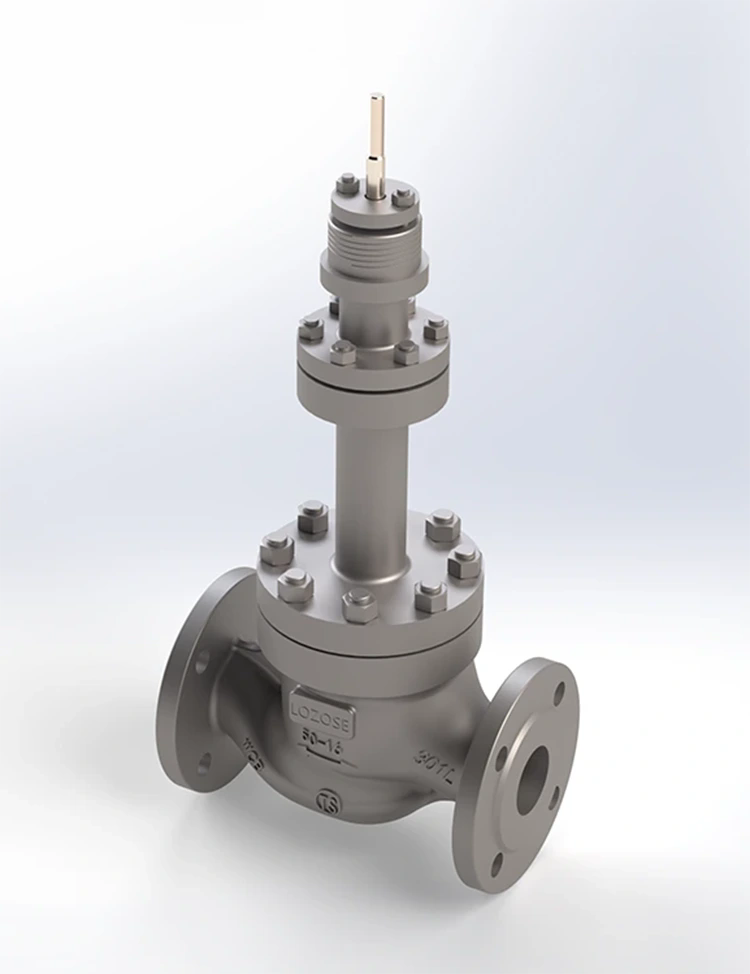
The Conventional Series Control Valve range includes linear, equal-percentage, and quick-opening flow characteristics. Its modular design allows different internal structures to be configured for different process requirements. The single-seat design uses a top-guided, unbalanced structure and an S-shaped flow passage. The manufacturer describes the passage as a low-resistance design intended to reduce pressure loss through the body while providing a high rated flow coefficient and a wide adjustment range.
In pressure-control service, these design features need to be considered alongside the actual differential pressure. A valve that performs well under moderate pressure drop may not be suitable for severe letdown involving flashing, cavitation, or high aerodynamic noise. Where a large pressure reduction is required, engineers should evaluate a purpose-designed multi-stage or anti-cavitation trim rather than assuming that a conventional single-seat trim can handle every condition.
Which Valve Parameters Should Engineers Evaluate for Oil and Gas Pressure Control?
Oil and gas service can involve natural gas, produced water, crude oil, steam, nitrogen, and process chemicals. These media differ in density, viscosity, compressibility, corrosiveness, and phase behaviour. Pressure-control valve specifications should therefore be reviewed as a complete operating package. Nominal diameter and nominal pressure are only the starting points; the selected valve must also meet the required capacity, temperature range, leakage class, material compatibility, and actuator performance.
The published specifications for the LOZOSE single-seat control valve provide a useful reference for preliminary engineering review. Final suitability must be confirmed against the project datasheet and actual process conditions.
| Parameter | Published specification | Engineering relevance |
| Nominal size | DN20 to DN300 | Provides a range of body sizes for different pipeline capacities. |
| Nominal pressure | 1.6, 2.5, 4.0, 6.4, and 10 MPa | Must be checked against the maximum design pressure and applicable piping class. |
| Rated flow coefficient, Cv | Linear: 8 to 1300; equal percentage: 8 to 1300, depending on size | Used in flow-capacity calculations and valve sizing. |
| Inherent flow characteristics | Linear, equal percentage, quick opening | Allows the characteristic to be matched to the control-loop behaviour. |
| Inherent rangeability | 30:1 or 50:1 | Indicates the stated controllable flow range under defined conditions. |
| Travel | 16, 25, 40, 60, and 100 mm | Selected according to valve size and trim configuration. |
| Signal range | 80 to 240 kPa | Reference pneumatic signal range for actuator operation. |
| Air supply pressure | 0.3 to 0.35 MPa | Must be available and stable at the actuator supply connection. |
| Leakage class | Hard seal Class IV; soft seal Class VI | Seat leakage requirements should be specified for the intended shut-off duty. |
| Working temperature | -196 to +560 degrees C, in different temperature configurations | Trim, packing, gasket, and body materials must suit the operating temperature. |
| Actuator options | Pneumatic diaphragm, pneumatic cylinder, and electric operation | Selection depends on required thrust, utilities, response, and control-system design. |
Material selection is particularly important in upstream and midstream facilities. Produced fluids may contain water, dissolved salts, carbon dioxide, hydrogen sulphide, sand, or other contaminants. The body, plug, seat, stem, packing, bellows, and gasket materials should be assessed against the full fluid composition, operating temperature, corrosion allowance, and project material requirements. The available body and bonnet materials include WCB, WC6, C5, LCB, CF8, and CF8M. Plug and seat options include 304 stainless steel, 304 with PTFE, and 304 with Stellite hardfacing.
| Component | Available materials or configuration | Selection consideration |
| Body and bonnet | WCB, WC6, C5, LCB, CF8, CF8M | Consider pressure-temperature rating, corrosion resistance, and process compatibility. |
| Plug and seat | 304, 304 with PTFE, 304 with Stellite | Choose according to leakage target, wear exposure, and fluid characteristics. |
| Packing | PTFE, flexible graphite | Check temperature, emissions requirements, and stem sealing conditions. |
| Bellows | 316L, Monel, HC276 | Evaluate when external stem leakage control is a key requirement. |
| Gaskets | 304 with graphite or PTFE; 2205 with graphite or PTFE; 316L with graphite or PTFE | Confirm compatibility with pressure, temperature, and process fluid. |
| Stem | 0Cr18Ni9, 2Cr13 | Review strength, corrosion exposure, and mechanical operating conditions. |
| Actuator | Pneumatic diaphragm, pneumatic cylinder, electric | Confirm thrust, travel, fail action, available utilities, and control signal. |
Lozose offers several configurations within its conventional product range. The single-seat valve is described for services involving steam, oil, ammonia, nitrogen, air, liquefied gas, and selected corrosive or special media. These examples do not mean that every material combination is suitable for every oilfield fluid. Sour-service applications, in particular, require a separate review of the fluid analysis, material qualification, and applicable project specifications.
What Risks Can Poor Pressure-Control Valve Selection Create?
An incorrectly selected valve can affect more than the pressure reading on a control-room display. It can contribute to unstable process operation, excessive energy loss, equipment stress, and increased maintenance requirements. The risks depend on the process medium, pressure differential, valve travel, and the severity of the operating conditions.
- Pressure hunting: An oversized valve or poorly matched flow characteristic can make the control loop overly sensitive. Repeated opening and closing movements may cause pressure fluctuations and accelerate wear on the trim and actuator.
- Cavitation and flashing: In liquid service, a large pressure drop may cause vapour bubbles to form. If the bubbles collapse as pressure recovers, cavitation can damage internal surfaces. Flashing occurs when vapour remains downstream because the pressure does not recover above the fluid vapour pressure.
- Gas noise and vibration: High gas velocity across the trim can generate aerodynamic noise and mechanical vibration. Severe service may require noise-reduction or multi-stage pressure-reduction designs.
- Material degradation: Corrosion, erosion, and chemical attack can reduce component life. Sand and other solids in produced fluids may further increase trim wear.
- Insufficient shut-off: A valve selected only for throttling performance may not meet the required seat leakage class when isolation is needed. Leakage class must be stated and verified through the specified inspection or testing procedure.
It is also important to distinguish normal pressure regulation from overpressure protection. A control valve modulates flow as part of the process control system. A pressure safety valve or another independent protective device is designed to protect equipment when pressure exceeds defined limits. The control valve should not be treated as a substitute for a properly engineered pressure relief system or emergency shutdown function.
For severe pressure-drop applications, a conventional single-seat design may not be the most appropriate choice. LOZOSE also lists low-noise, high-pressure, cage-guided, and multi-stage control valve configurations. The final selection should follow a review of inlet and outlet pressure, flow rate, fluid phase, vapour pressure, critical pressure, noise limits, and expected operating cases.
How Can Operators Improve Long-Term Pressure-Control Reliability?
Reliable pressure control depends on more than the valve body. The transmitter, controller, positioner, actuator, instrument-air supply, impulse line, and piping arrangement all influence the performance of the control loop. A well-sized valve can still operate poorly if the pressure measurement is inaccurate, the actuator receives unstable air supply, or the control signal is incorrectly configured.
Before commissioning, engineers should verify the valve tag, flow direction, pressure class, flange standard, actuator action, signal range, and fail position against the approved datasheet. The instrument team should check the pressure transmitter range and calibration, confirm positioner response, and conduct a functional stroke test. Where the process requires a specific failure response, the cause-and-effect documentation should identify how the valve behaves following loss of air, electrical power, or control signal.
During operation, maintenance teams should monitor valve travel, controller output, pressure deviation, response time, and signs of leakage or vibration. A valve that repeatedly operates near its travel limit may indicate a sizing or process-capacity issue. Frequent position changes may point to poor tuning, changing process conditions, or mechanical friction. Inspection intervals should be based on service severity, operating history, manufacturer recommendations, and site maintenance procedures.
Our engineering review should begin with the process datasheet rather than a general product category. Useful information includes the fluid composition, normal and maximum flow rates, minimum and maximum inlet pressure, required outlet pressure, operating temperature, differential pressure, allowable noise level, and required leakage class. For gas service, compressibility and expansion effects must be included in the sizing calculation. For liquid service, vapour pressure and the possibility of cavitation or flashing need to be evaluated.
At the manufacturing and supply stage, our factory can use the confirmed technical requirements to identify an appropriate body size, trim arrangement, material combination, and actuator configuration. The project specification should also define inspection records, pressure testing, seat leakage testing, material documentation, and any additional requirements for hazardous or sour service. These checks provide a clearer basis for verifying that the supplied valve matches the intended operating duty.
Conclusion: How Should Oil and Gas Facilities Choose the Right Pressure-Control Valve?
Control valves are essential to pressure management because they provide continuous, adjustable control of process flow across production, separation, compression, treatment, and utility systems. Their performance depends on correct sizing, suitable flow characteristics, compatible materials, reliable actuation, and an accurate control loop. A valve should be selected for the actual operating envelope, not simply by matching its nominal size to the pipeline.
Zhejiang Lozose Intelligent Control Instrument Co., Ltd. provides conventional control valve configurations with different sizes, pressure ratings, trim materials, leakage classes, flow characteristics, and actuator options. If you are specifying a pressure-control valve for an oil and gas production facility, contact our team with your process conditions and technical datasheet. We can review the application requirements and help identify a suitable valve configuration for your project.
Frequently Asked Questions
Why are control valves used on oil and gas production separators?
Control valves regulate gas or liquid flow from a separator to help maintain the vessel's required operating pressure or liquid level. For pressure control, the valve usually modulates the gas outlet flow in response to a pressure transmitter and controller. Correct sizing is important because separator inlet conditions and gas production rates can change during operation. The selected valve must also account for pressure drop, gas properties, noise, and the possibility of liquid carryover.
Can a conventional single-seat control valve handle high-pressure oil and gas service?
Suitability depends on the valve's rated pressure, differential pressure, flow capacity, temperature, trim design, and material compatibility. A single-seat valve may be suitable for specified duties within its approved operating envelope, but severe pressure letdown, cavitation, flashing, or high gas noise may require a dedicated high-pressure or multi-stage design. Engineers should confirm the actual operating cases and manufacturer sizing data before approving a valve for high-pressure service.
What is the difference between a pressure-control valve and a pressure safety valve?
A pressure-control valve continuously adjusts flow to maintain a process pressure setpoint during normal operation. A pressure safety valve is a protective device designed to open at a defined pressure to prevent equipment from exceeding its allowable pressure limit. They perform different functions and should not be treated as interchangeable. The control system, relief devices, and emergency shutdown functions must be engineered together according to the facility's process safety requirements.