

How to Size a Cast Steel Check Valve Correctly Without Creating Flow Bottlenecks
2026-07-17
Selecting the right valve size is often more critical than choosing the pressure class or end connection. An oversized unit wastes capital and invites chatter, while an undersized one generates excessive velocity, erosion, and premature failure. For engineers and procurement specialists, the real challenge lies in balancing line diameter, flow velocity, and pressure drop—all while ensuring the Cast Steel Check Valve responds reliably to changing system conditions. At Hanno, we have worked with hundreds of piping systems across oil, gas, petrochemical, and power generation sectors, and we consistently see that proper sizing starts with understanding the valve’s function as a dynamic flow-responsive device, not just a piece of pipe.
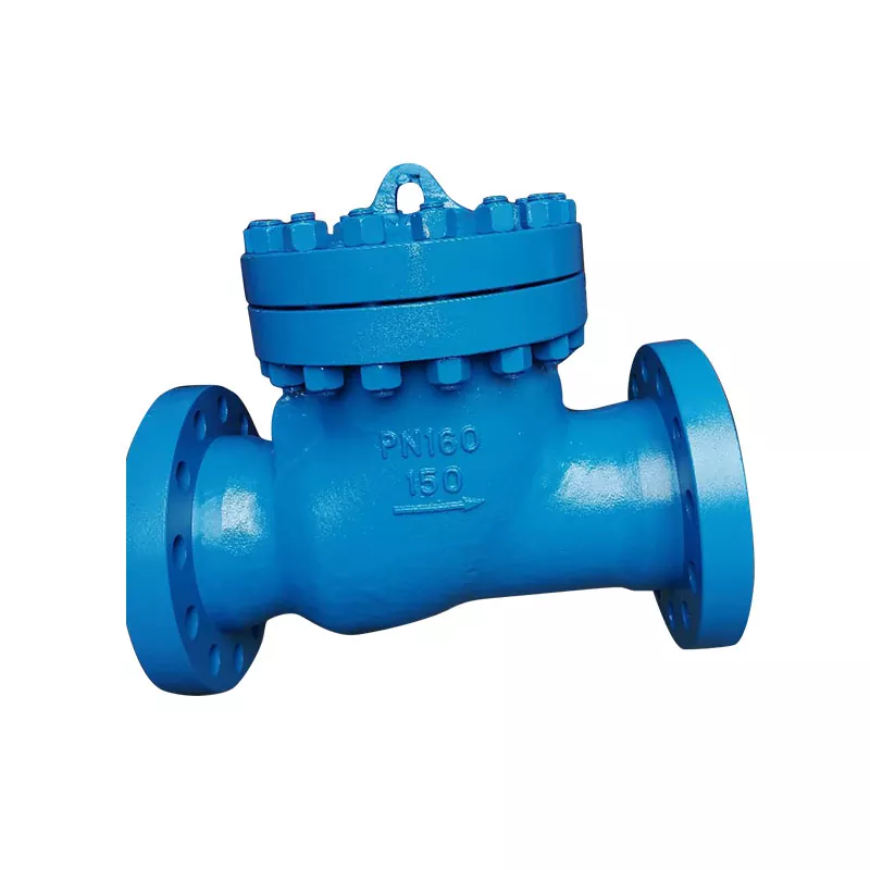
The Core Sizing Formula – Velocity First
The industry standard for sizing any Cast Steel Check Valve begins with calculating the minimum flow velocity required to keep the disc fully open. For swing-type designs, that threshold typically falls between 1.5 m/s and 3.0 m/s for liquid services. Below this range, the disc oscillates, causing accelerated wear on the hinge and seat. Above 4.5 m/s, erosion becomes a serious risk, especially with entrained solids or two-phase flows.
The fundamental equation is:
Q = A × V
(Flow rate = Cross-sectional area × Velocity)
Rearrange to solve for the required internal diameter (d):
d = √(4Q / πV)
Where Q is in m³/s, V is in m/s, and d is in meters. This gives a theoretical bore size. However, the actual flow coefficient (Cv) provided by the manufacturer must be matched against the system’s allowable pressure drop. Hanno recommends always using the Cv method for final verification, because it accounts for the internal geometry—disc shape, hinge resistance, and seat contour—which the simple area calculation ignores.
Step-by-Step Sizing Procedure
| Step | Action | Critical Parameter |
|---|---|---|
| 1 | Define normal, minimum, and maximum flow rates | Qmin, Qnorm, Qmax (m³/h) |
| 2 | Determine fluid density and viscosity | Affects Reynolds number |
| 3 | Select target velocity range (2.0 – 3.5 m/s for liquids) | Prevents chatter and erosion |
| 4 | Calculate preliminary bore diameter | Use d = √(4Q/πV) |
| 5 | Compare with standard pipe schedules (DN, NPS) | Round up to nearest standard size |
| 6 | Obtain Cv curve from Hanno datasheet | Verify pressure drop at Qnorm |
| 7 | Check ΔP ≤ 10% of system inlet pressure | Avoids pump overloading |
Common Pitfalls in Real Projects
Many engineers rely on line size alone—if the pipe is 6-inch, they order a 6-inch Cast Steel Check Valve. This works only when the line velocity is designed for that exact diameter. In recirculation lines, bypass loops, or variable-speed pump discharges, the actual flow can drop to 30–40% of nominal, making the valve effectively “too large.” The result: the disc never reaches full lift, leading to continuous fluttering and premature seat leakage.
Conversely, in high-flow condensate or boiler feedwater applications, a valve sized by pipe diameter may create a velocity exceeding 6 m/s. Over one year, that extra 2 m/s can erode the seat ring and reduce the valve’s service life by more than half. Hanno always advises calculating at three flow conditions: minimum, normal, and maximum, then selecting the size that keeps the disc stable across all three.
Frequently Asked Questions About Cast Steel Check Valves
Q1: What happens if I install a Cast Steel Check Valve that is one size larger than the line pipe?
A: Installing a valve one nominal size larger than the pipe (e.g., an 8-inch valve on a 6-inch line with reducers) is sometimes done to lower pressure drop, but it introduces significant risks. The reduced velocity at the valve inlet may not generate enough dynamic force to fully lift the disc, especially at low flow rates. This causes the disc to hover near the seat, resulting in constant vibration, noise, and rapid wear of the hinge pin and bushing. Additionally, the sudden expansion and contraction from the reducers create turbulence that can misalign the disc approach flow, leading to off-centre seating and leakage. Unless the system operates at high flow 90% of the time, Hanno recommends matching the valve to the smallest pipe section velocity, not the largest.
Q2: How does fluid viscosity affect the sizing calculation for a Cast Steel Check Valve?
A: Viscosity directly influences the Reynolds number, which changes the drag coefficient on the disc. For low-viscosity fluids like water or light hydrocarbons, standard Cv tables are accurate. However, for heavy crude oils, molasses, or polymer solutions with viscosity above 300 cP, the disc experiences significantly higher resistance to opening. This means the required opening velocity increases by 20–40% compared to water. Failing to account for viscosity leads to a valve that remains partially closed, creating a permanent pressure drop of 0.5–1.5 bar even at design flow. Hanno provides corrected Cv factors for viscous services in our technical manuals, and we strongly recommend using computational fluid dynamics (CFD) or manufacturer-specific viscosity multipliers when sizing for non-Newtonian fluids.
Q3: Can I use the same sizing method for both swing and tilting-disc Cast Steel Check Valves?
A: No. Swing-type check valves rely on gravitational closure and have a longer disc stroke, requiring a higher minimum velocity (typically 2.5–3.5 m/s) to achieve full opening. Tilting-disc designs, on the other hand, use a shorter pivot arc and lighter disc construction, allowing stable operation at velocities as low as 1.2 m/s. Additionally, swing valves have a higher pressure drop at low flow due to the disc hanging in the flow path, while tilting-disc valves offer a nearly streamlined profile when open. Therefore, the target velocity range, Cv curve, and closure response time differ substantially. Always consult the specific Hanno model datasheet—never apply generic rules across different internal geometries.
Final Verification – The 10% Rule
Before finalising your selection, run a pressure-drop check at the maximum flow rate. The total loss through the Cast Steel Check Valve should not exceed 10% of the upstream gauge pressure for pump discharge systems, or 5% for gravity-fed lines. If the calculated ΔP is higher, move up one size and recalculate velocity—but ensure the new size still meets the minimum opening velocity at the lowest expected flow.
Contact Us for a Sizing Review
Every piping network has unique transients, thermal cycles, and maintenance intervals that generic software cannot anticipate. Hanno offers free preliminary sizing verification for any new or retrofit project. Our engineering team provides a written recommendation including velocity calculations, Cv selection, and spring setting (if applicable) within 24 hours. Do not leave performance to guesswork; let Hanno help you specify the right Cast Steel Check Valve the first time.