

How to Install a Flanged PN16 Stainless Steel Hard-Seal Gate Valve Like a Pro
2026-07-16
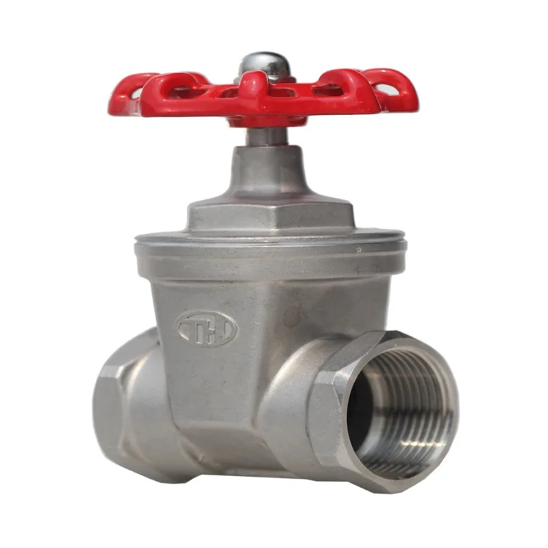
Proper installation of a PN16 Stainless Steel Hard-Seal Gate Valve directly determines its service life, sealing performance, and operational safety. While the valve itself is engineered for durability in high-pressure and high-temperature systems, incorrect fitting remains the leading cause of premature failure. This guide walks through every critical step, from pre-inspection to torque tightening, while addressing the most frequent on-site challenges.
Pre-Installation Checklist
Before lifting or bolting any PN16 Stainless Steel Hard-Seal Gate Valve, complete the following verification table:
| Inspection Item | Acceptance Criteria | Action if Failed |
|---|---|---|
| Nameplate data | PN16 rating, stainless steel grade (CF8/CF8M), bore size match | Return to supplier |
| End-face protection | Flange gasket surfaces free from scratches, dents, or rust | Refinish or replace |
| Internal cleanliness | No debris, welding slag, or shipping plugs left inside | Flush with clean water/air |
| Actuator/gear operator | Manual handwheel turns freely through full stroke | Lubricate or repair stem threads |
| Gasket & fastener kit | New spiral-wound gasket + ASTM A193 B8 studs/nuts | Do not reuse old gaskets |
Step-by-Step Installation Procedure
1. Pipe Preparation
Cut and bevel the pipeline ends according to ASME B16.25. Remove all burrs and clean the inside bore thoroughly. For flanged connections, the pipe flange face must be parallel to the valve flange within 0.5 mm per meter.
2. Valve Positioning
Orient the PN16 Stainless Steel Hard-Seal Gate Valve with the stem vertical (preferred) or inclined no more than 15° from vertical. Never install with the stem pointing downward—this traps condensate and accelerates stem seal wear. Ensure sufficient clearance above the handwheel for full stroke operation.
3. Gasket Placement
Center a new, correct-size spiral-wound gasket (316SS/graphite filler) between the flanges. Do not apply sealant or grease on the gasket surface unless specified by the gasket manufacturer—this can hinder metal-to-metal contact and increase creep relaxation under PN16 pressure (16 bar working pressure).
4. Stud & Nut Insertion
Insert all studs evenly. Lubricate threads with anti-seize compound (nickel-based for stainless steel) to prevent galling. Hand-tighten all nuts in a star pattern.
5. Torque Tightening (Critical Step)
Use a calibrated torque wrench. Tighten in three incremental passes:
| Pass | Torque (% of final) | Pattern |
|---|---|---|
| 1st | 30% | Star (opposite pairs) |
| 2nd | 70% | Star (offset from 1st) |
| 3rd | 100% | Sequential clockwise (final even gasket compression) |
Final torque values depend on stud diameter—refer to ASME PCC-1. For M24 studs, typical final torque is 350–400 N·m. Over-torquing distorts the valve body and causes binding of the gate wedge.
6. Post-Installation Stroke Test
Open and close the valve fully three times under no pressure. Confirm the handwheel turns smoothly and the stem indicator shows full travel (zero to 100%). Then pressurize the system gradually to PN16 rating and check all flange joints for leakage.
Common Mistakes to Avoid
-
Using the valve as a pipe anchor – The PN16 Stainless Steel Hard-Seal Gate Valve must be supported independently; piping stress can warp the body.
-
Installing without axial alignment – Misaligned flanges create bending loads on the stem, leading to uneven gate seating.
-
Ignoring flow direction – Although this gate valve is bidirectional, some designs have a preferred pressure side—check the arrow cast on the body.
FAQ – PN16 Stainless Steel Hard-Seal Gate Valve Common Questions
Q1: Can I install a PN16 Stainless Steel Hard-Seal Gate Valve in a vertical pipeline with flow upward?
A1: Yes, you can install it vertically, but the stem should remain in the vertical plane with the handwheel at the top. Flow direction (upward or downward) does not affect the gate’s sealing because this valve uses metal-to-metal wedging action. However, for vertical lines with high upward velocity, consider a reduced-bore design to minimise disc flutter. Always verify that the actuator weight does not rest entirely on the stem threads—use a support bracket for motorised versions. Under PN16 pressure, the hard-faced Stellite seat rings handle erosive particles better than soft-seat designs, making vertical installation acceptable in slurry services.
Q2: What gasket type and material are recommended for a flanged PN16 Stainless Steel Hard-Seal Gate Valve handling 200°C superheated water?
A2: For 200°C and PN16 rating, a spiral-wound gasket with a 316SS outer ring and flexible graphite filler is the industry standard. Avoid pure PTFE gaskets because they creep excessively above 150°C. The gasket’s internal bore must match the valve’s full-port diameter (not the pipe ID) to avoid turbulence. Recommended compression stress: 140–180 MPa on the gasket area. Torque the flange bolts to the upper half of the recommended range because graphite relaxes about 8–12% after thermal cycling. After the first heat-up to 200°C, perform a hot-retorque of all nuts at operating temperature within 24 hours—this compensates for bolt relaxation and ensures leak-free joint integrity.
Q3: How do I verify that my installation does not impose pipeline stress on the PN16 Stainless Steel Hard-Seal Gate Valve body?
A3: Use the “dial gauge method” during flange bolting. Mount a magnetic-base dial indicator on the valve body, with the probe touching the adjacent pipe flange. While tightening the studs, monitor the indicator—if the pipe flange moves more than 0.2 mm relative to the valve body, stop and realign the pipe hangers. Alternatively, use laser alignment tools for large-bore valves. After full bolting, check that the handwheel operates without increased resistance (compared to the shop-floor test). A 15% rise in operating torque suggests bending stress. For critical services, pipe supports must be installed within 300 mm of each valve flange to transfer weight away from the body. Remember, the PN16 Stainless Steel Hard-Seal Gate Valve is a pressure-retaining shell, not a structural support.
Maintenance After First 100 Cycles
After the initial commissioning and 100 full open/close cycles, re-check flange bolt torque (cold condition). Inspect the stem packing for any weepage—if present, gently tighten the gland bolts by 1/8 turn increments, evenly on both sides. Record all torque values in a log for future trending.
Why Choose Tianhong for Your Critical Valve Needs
Every step above reflects decades of field experience that Tianhong engineers embed into every PN16 Stainless Steel Hard-Seal Gate Valve. From precision-machined wedge faces to 100% hydrostatic testing at 1.5× PN16, Tianhong valves are built to withstand thermal cycling, abrasive media, and demanding shut-off duties. Our technical support team provides site-specific torque charts, gasket selection guides, and remote troubleshooting—because correct installation is only the beginning.
Need a custom torque procedure or on-site training for your team? Contact Tianhong today via our global service portal or email your project specifications to our engineering desk. We respond within 4 business hours with detailed recommendations, CAD drawings, and a dedicated installation checklist tailored to your pipeline class and fluid conditions. Let’s make your valve installation flawless—reach out now.