

How to Correctly Size a Cage Type Single Seat Control Valve for Liquid Service
2026-08-19
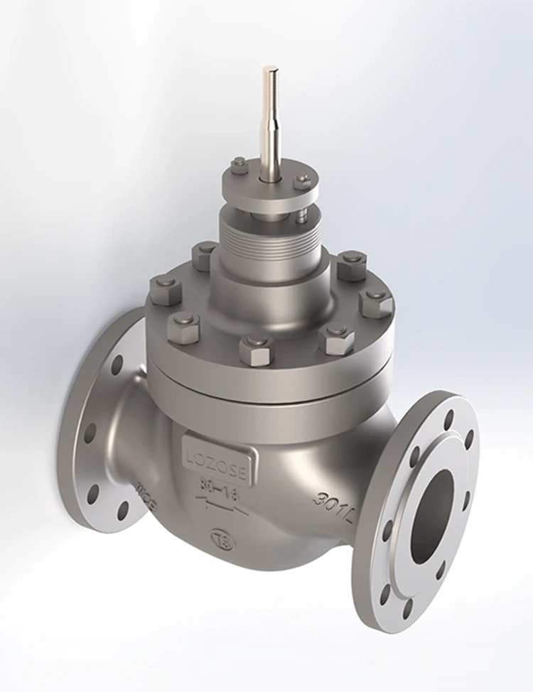
Sizing a control valve for liquid flow is one of the most critical responsibilities a process engineer faces. An undersized valve starves the system, causing production bottlenecks, while an oversized valve hunts continuously, wears out its trim prematurely, and leads to costly unplanned shutdowns. For LOZOSE, a manufacturer with over two decades of expertise in precision flow control, the Cage Type Single Seat Control Valve represents the optimal fusion of mechanical stability, noise attenuation, and bubble-tight shut-off. Yet even the finest valve performs poorly if its size does not match the process demand. This guide walks through the internationally recognized IEC 60534-2-1 sizing methodology, incorporating practical corrections for piping geometry, viscous fluids, and cavitation-prone services, ensuring that your LOZOSE Cage Type Single Seat Control Valve delivers decades of reliable, stable operation.
Essential Data Collection – The Foundation of Correct Sizing
Before performing any calculation, compile these six fundamental parameters from your process datasheet. Accuracy at this stage determines the reliability of every subsequent step.
| Parameter | Symbol | Typical Unit | Practical Source |
|---|---|---|---|
| Maximum volumetric flow rate | Qmax | m³/h or gpm | Pump curve or vessel mass balance |
| Minimum upstream pressure | P1 (min) | kPa or psia | Pump NPSH calculation or supply header |
| Maximum downstream pressure | P2 (max) | kPa or psia | Receiver vessel pressure or back-pressure valve |
| Liquid temperature at max flow | Tmax | °C or °F | Process design basis (summer condition) |
| Liquid density | ρ | kg/m³ | Physical property database (e.g., DIPPR) |
| Liquid vapor pressure | Pv | kPa absolute | Antoine equation at Tmax |
Critical engineering rule: Always size using the maximum flow rate combined with the minimum available upstream pressure and the maximum downstream pressure. This produces the worst-case (smallest) pressure drop, which yields the largest required Cv—a conservative and safe approach.
Calculate the Required Flow Coefficient – The Core Equation
The universal liquid sizing equation for turbulent, non-flashing, Newtonian liquids is straightforward. For US customary units:
Cv = Q × √(SG / ΔP)
Where:
-
Cv = flow coefficient (US gallons per minute of water at 60°F with a 1 psi drop)
-
Q = flow rate in US gallons per minute
-
SG = specific gravity (dimensionless, reference = water at 60°F)
-
ΔP = P1 – P2 in psi (differential pressure across the valve)
For metric units (m³/h and bar), the equivalent expression is:
Cv = 1.156 × Q_metric × √(SG / ΔP_bar)
The Piping Geometry Factor (Fp) – A Necessary Correction
In real installations, the control valve is rarely mounted between straight, full-bore pipes of the same diameter. Reducers, expanders, elbows, and block valves create additional turbulence and pressure losses that reduce the valve's effective capacity. The Fp factor corrects the theoretical Cv for these fitting losses.
LOZOSE publishes Fp curves for every Cage Type Single Seat Control Valve size and end connection style. If curves are unavailable, use this conservative approximation:
Fp = 1 / √(1 + ΣK × (Cv / d²)²)
Where:
-
d = internal port diameter of the valve (inches)
-
ΣK = sum of resistance coefficients of all attached fittings (use Crane Technical Paper No. 410 values)
| Installation Type | Typical ΣK | Fp (for 2" valve in 3" line) |
|---|---|---|
| Concentric reducers, long radius | 0.5 – 0.8 | 0.92 – 0.95 |
| Eccentric reducers, short radius | 1.0 – 1.5 | 0.85 – 0.90 |
| Full-bore matching line size | 0.0 | 1.00 |
Practical rule: If the line size equals the valve size, Fp ≈ 1.0 and can be ignored. If the valve is one size smaller than the line, always apply Fp—it typically reduces the calculated Cv by 5% to 15%.
Check for Flashing and Cavitation – The Silent Destroyers
The standard Cv equation assumes that the liquid remains entirely in the liquid phase throughout the valve. This assumption fails when the downstream pressure (P2) falls below the liquid's vapor pressure (Pv) at the flowing temperature.
| Condition | Criterion | Recommended Action |
|---|---|---|
| Non-flashing | P2 > Pv | Use the standard Cv equation directly |
| Flashing | P2 < Pv | Use the flashing Cv equation with vapor mass fraction (q) – consult IEC 60534-2-1e |
| Cavitation | P2 > Pv but P1 – P2 exceeds the allowable ΔPmax | Increase valve size, choose a larger outlet, or select anti-cavitation trim |
For LOZOSE Cage Type Single Seat Control Valve, our multi-stage cage trims (available with 2, 3, or 4 pressure-reducing stages) are specifically engineered to stage the pressure drop across multiple resistance elements. This raises the vena contracta pressure well above Pv, effectively eliminating cavitation damage even at differential pressures up to 150 bar (2175 psi) on cold water service.
Cavitation limit quick-check formula:
ΔPmax = Kc × (P1 – Pv)
Where Kc is the cavitation index. For a standard globe-style single-seat valve without cage guidance, Kc ≈ 0.35 – 0.45. For LOZOSE cage-guided designs, the cage windows break the flow jet into multiple small streams, raising Kc to 0.65 – 0.75. With our proprietary tortuous-path anti-cavitation cages, Kc can reach 0.90 or higher.
Validation step: If your calculated ΔP exceeds ΔPmax, do not proceed. You must either:
-
Select a larger valve size (reduces ΔP across the trim),
-
Choose a LOZOSE multi-stage cage with additional pressure-reducing stages,
-
Or install two valves in series to divide the total pressure drop.
Viscous Flow Correction – When Reynolds Number Drops Below 10,000
For low-viscosity liquids like water, condensate, or light hydrocarbons (Re > 10,000), the standard Cv equation is accurate. However, for heavy oils, polymer melts, or syrups with viscosities above 100 cSt, laminar flow conditions prevail, and the standard equation overestimates the valve capacity significantly.
LOZOSE recommends this two-step procedure for viscous services:
Step 1 – Calculate an initial Cv using the standard equation (ignore viscosity for this step).
Step 2 – Compute the Reynolds number at the valve seat:
Re = (Q × ρ) / (µ × √(Cv_initial))
Where:
-
Q = flow rate in consistent units
-
ρ = density (kg/m³)
-
µ = dynamic viscosity (cP or mPa·s)
-
Cv_initial = the value from Step 1
If Re < 10,000, apply the FR correction factor from the ISA-75.01.01 standard charts. Multiply your required Cv by FR (which ranges from 1.05 to over 2.0 for highly viscous fluids). The corrected required Cv becomes:
Cv_required_corrected = Cv_initial × FR
For most water-based services, FR = 1.0 and this step can be skipped.
Select the Actual Valve Size – The Practical Decision
Compare your final corrected required Cv (with Fp, FR, and cavitation adjustments applied) against the rated Cv table for LOZOSE Cage Type Single Seat Control Valve offerings.
| Valve Size (inch) | Port Diameter (mm) | Rated Cv (Full Open, Cage Trim) | Recommended Operating Zone (% of Rated Cv) |
|---|---|---|---|
| 1/2" | 12.7 | 4.2 | 20% – 80% |
| 1" | 25.4 | 12.5 | 20% – 80% |
| 1.5" | 38.1 | 28.0 | 20% – 80% |
| 2" | 50.8 | 50.0 | 20% – 80% |
| 3" | 76.2 | 110 | 20% – 80% |
| 4" | 101.6 | 190 | 20% – 80% |
| 6" | 152.4 | 430 | 20% – 80% |
| 8" | 203.2 | 780 | 20% – 80% |
Selection rule – The 1.25x Margin:
Choose the smallest standard valve size whose rated Cv is at least 1.25 times your corrected required Cv. This margin accomplishes three goals:
-
It ensures the valve operates between 30% and 70% of full travel under normal flow conditions.
-
It provides reserve capacity for future process turndown or fouling.
-
It avoids the non-linear region near full closure, where resolution and repeatability deteriorate.
Example: If your corrected required Cv = 40, the 1.25× margin gives 50. The 2" valve (rated Cv = 50) is the correct choice. Do not jump to the 3" valve (Cv = 110) unless you have a specific future expansion plan.
Final Verification – Noise and Actuator Thrust
Even with a mathematically correct Cv, two additional checks are mandatory before finalizing your selection.
Aerodynamic Noise Prediction
For liquid services, noise primarily originates from hydrodynamic cavitation (sharp, crackling sound), mechanical vibration of the plug and cage, and turbulent flow through cage windows. LOZOSE recommends using the IEC 60534-8-4 method for liquid noise prediction. As a quick screening rule: if your ΔP exceeds 20 bar (290 psi) and the outlet velocity exceeds 15 m/s (50 ft/s) in water, noise levels may approach or exceed 85 dBA at 1 meter. For these cases, select a LOZOSE low-noise cage with staggered window patterns, which can reduce overall sound pressure by 6 to 12 dBA without changing the valve size.
Actuator Closing Thrust
The actuator must generate sufficient force to overcome the unbalanced pressure force acting on the plug and to seat the plug tightly against the seat ring under maximum shut-off differential pressure.
F_required = (ΔP_shutoff × Seat_Area) + F_seating + F_friction
For LOZOSE Cage Type Single Seat Control Valve, the cage guides the plug axially through its entire travel, which reduces side-loading and friction by approximately 30% compared to unguided stem designs. This means a smaller, more economical actuator can achieve the same shut-off class (ANSI/FCI 70-2 Class IV or V). Always multiply the calculated thrust by a safety factor of 1.5 to account for packing friction and supply pressure variations.
Cage Type Single Seat Control Valve – FAQ
Q1: Why does my Cage Type Single Seat Control Valve show a lower rated Cv than a conventional single-seat valve with the same port diameter?
A1: This is not a defect—it is a deliberate engineering trade-off. The cage inside the valve contains precisely machined windows or drilled holes that intentionally distribute the total pressure drop across multiple throttling orifices. This staged pressure reduction reduces the rated Cv by 10% to 30% compared to an un-caged single-seat valve of the same nominal port size. However, that apparent "capacity loss" brings substantial benefits: the cage guides the plug concentrically, eliminating lateral vibration and stem bending; it protects the seat ring from high-velocity, particle-laden flow; and it raises the cavitation index (Kc) from roughly 0.35 to over 0.70. For LOZOSE valves, we publish two distinct Cv values for every model—the full-port theoretical Cv (without cage effects) and the cage-rated Cv (with actual flow testing). For all sizing purposes, you must use the cage-rated Cv. If your system requires the full theoretical Cv, consider a LOZOSE high-capacity cage design with larger window openings or a multi-hole cage specifically optimized for maximum flow area. Our engineering team can suggest alternative cage patterns upon request.
Q2: How do I correctly size a Cage Type Single Seat Control Valve for a liquid service that contains 5% to 10% dissolved gas, such as raw seawater with entrained air or hydrocarbon streams with dissolved methane?
A2: The standard liquid equation fails for two-phase or gas-entrained mixtures because the gas phase expands adiabatically across the valve, absorbing pressure energy and reducing the effective density of the fluid. The most widely accepted rigorous method is the homogeneous equilibrium model (HEM), which treats the mixture as a single pseudo-fluid with averaged properties. The recommended procedure is to calculate the total mass flow rate (liquid mass + gas mass) in kg/s, compute the homogeneous density at upstream conditions using the ideal gas law for the gas phase and the liquid density at P1 and T, then use the compressible flow equation with an effective specific heat ratio (k ≈ 1.0 to 1.05 for gas–liquid mixtures). Convert the resulting mass flux into an equivalent Cv, then multiply by a two-phase correction factor typically between 1.2 and 1.4 (obtained from IEC 60534-2-1e Annex F). For field practice, many engineers simplify by sizing the valve as if it were handling only the liquid phase at the same mass flow, then adding 20% to the required Cv as a conservative buffer. However, for accurate results, LOZOSE offers complimentary two-phase sizing studies using validated CFD-based tools. Simply provide your gas mass fraction, upstream pressure, temperature, and gas composition, and our application engineers will deliver a fully documented sizing report within two working days.
Q3: What is the absolute maximum differential pressure that a Cage Type Single Seat Control Valve can withstand before cavitation becomes mechanically destructive, and how does the cage trim specifically extend that limit compared to a conventional seat?
A3: For a standard, un-caged single-seat globe valve, the maximum non-cavitating pressure drop is approximately ΔPmax = Kc × (P1 – Pv), with Kc typically between 0.35 and 0.45. This means if your upstream pressure is 50 bar and the vapor pressure is 5 bar, the allowable ΔP before cavitation onset is only about 0.40 × 45 = 18 bar. Beyond this point, vapor bubbles form at the vena contracta and collapse downstream, causing pitting, erosion, and rapid seat failure. Now consider the same service with a LOZOSE Cage Type Single Seat Control Valve. The cage contains multiple rows of flow passages that break the high-velocity jet into many small, independent streams. Each stream undergoes a partial pressure drop, and the downstream jets merge with sufficient turbulence to keep the local pressure above Pv at every point. This multi-stage effect raises the effective Kc to between 0.75 and 0.90, depending on the cage design. For our top-tier tortuous-path cages, we have verified Kc = 0.92 on water test stands at ΔP up to 120 bar (1740 psi) without measurable cavitation erosion after 500,000 cycles. The absolute upper limit is not set by cavitation alone but by the valve body's pressure–temperature rating per ASME B16.34. For a Class 600 body, the maximum allowable working pressure at 100°C is approximately 99 bar (1435 psi). For extremely high differential pressures (above 100 bar), we strongly recommend either installing two LOZOSE Cage Type Single Seat Control Valve in series, dividing the total ΔP equally, or selecting our 4-stage anti-cavitation cage, which reduces the pressure drop per stage to well below the critical threshold.
Final Pre-Purchase Checklist
Before submitting your purchase requisition for a LOZOSE Cage Type Single Seat Control Valve, confirm every item on this list:
-
Required Cv calculated for maximum, normal, and minimum flow conditions.
-
Piping geometry factor (Fp) applied when valve size differs from line size.
-
Viscosity correction factor (FR) applied for Re < 10,000.
-
Cavitation check performed using Pv at the maximum flowing temperature.
-
Valve size selected with a 1.25× margin to ensure 30% – 70% travel range.
-
Noise level predicted and confirmed below 85 dBA at 1 meter.
-
Actuator closing thrust verified for maximum differential shut-off pressure.
Contact LOZOSE – Let Our Engineers Size Your Valve with Precision
Sizing a Cage Type Single Seat Control Valve is not merely a spreadsheet exercise—it is an iterative engineering process that demands cross-checks for cavitation, noise, actuator stiffness, piping dynamics, and future process turndown. One misapplied correction factor can lead to years of valve instability, premature trim replacement, and unplanned production losses.
LOZOSE provides a complimentary, no-obligation sizing audit for every inquiry. Our in-house application engineers utilize certified ISA-75.01.01 and IEC 60534-2-1 software packages, validated against our in-house flow laboratory with real test-stand data for each cage trim variant we produce. Whether you require a 1/2" stainless steel valve for a pharmaceutical injection line or an 8" carbon steel valve for a municipal water pumping station, we deliver a comprehensive datasheet that includes full Cv curves across 0% to 100% travel, predicted noise spectra under all operating conditions, cavitation index plots with safety margins indicated, recommended actuator spring range and bench-set pressure, and a detailed two-page sizing report signed by our lead engineer.
Get your valve sized correctly from the very first day—avoid oversizing, hunting, and trim erosion forever.
Our engineering team responds with a preliminary valve recommendation within one business day—no complex forms, no hidden fees, just transparent, data-driven engineering. Let us help you select a Cage Type Single Seat Control Valve that delivers stable control, minimal maintenance, and maximum service life from the moment it is installed. Contact LOZOSE now.