

How Temperature Extremes Compromise the PTFE Lining in Control Valves
2026-07-15
For engineers and plant operators managing aggressive chemical flows, the Single Seat Fluorine Lined Control Valve is a trusted workhorse. However, few realize that temperature is not merely a process parameter—it is a direct threat to the PTFE lining integrity. When that lining fails, the entire Single Seat Fluorine Lined Control Valve becomes a liability, leading to unplanned downtime, safety hazards, and costly media replacement. At LOZOSE, we have analyzed hundreds of field failures and compiled this technical deep-dive to help you predict, prevent, and manage thermal effects on your critical flow control equipment.
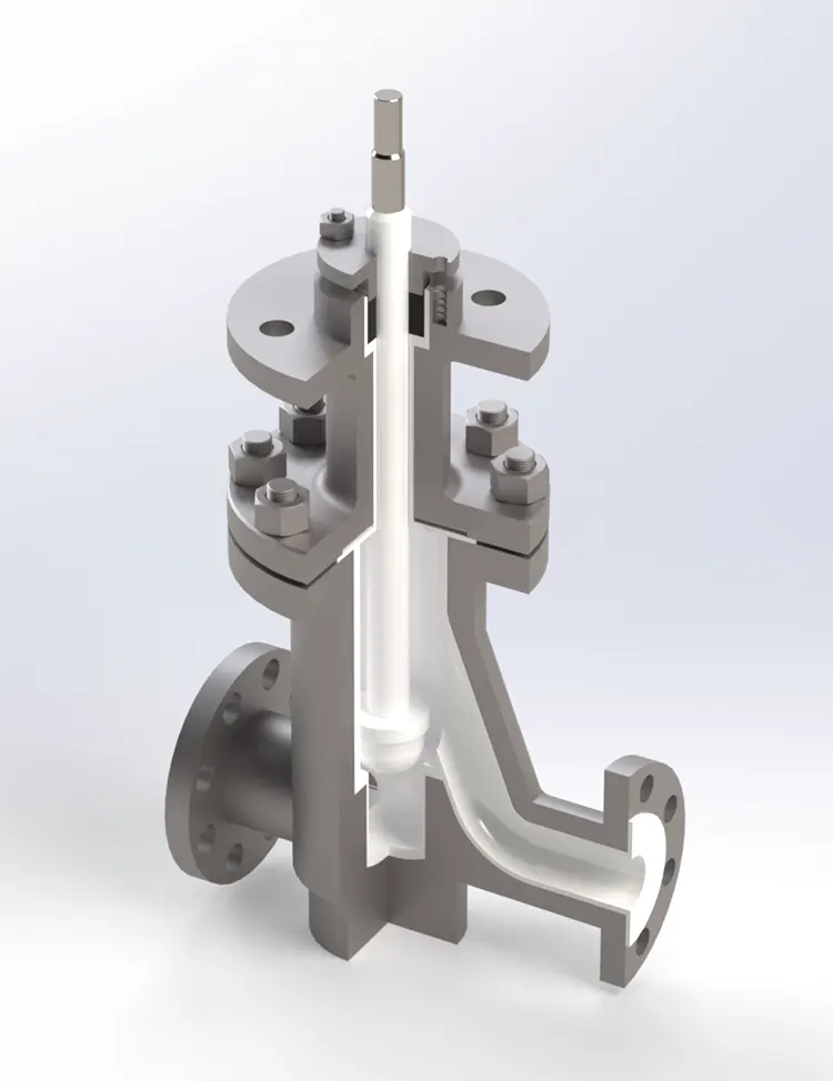
The Thermal Behavior of PTFE: A Double-Edged Sword
Polytetrafluoroethylene (PTFE) offers exceptional chemical resistance, but its mechanical properties are highly temperature-dependent. The lining in a Single Seat Fluorine Lined Control Valve experiences three distinct thermal regimes:
| Temperature Range | PTFE Behavior | Primary Risk to Valve |
|---|---|---|
| -20°C to +80°C | Stable, elastic | Minimal; ideal operating window |
| +80°C to +150°C | Gradual softening; creep increases | Seat deformation, torque rise |
| +150°C to +200°C | Rapid expansion; crystalline transition | Leakage, stem seal extrusion |
| > +200°C | Decomposition; toxic off-gassing | Catastrophic failure |
The coefficient of thermal expansion for PTFE is roughly 10–15 times that of carbon steel. This mismatch means that as process temperature rises, the PTFE lining expands faster than the metal body, creating internal compressive stresses. Conversely, sudden cooling can shrink the liner away from the cage, creating clearance gaps that invite particulate erosion.
Three Critical Failure Mechanisms Linked to Heat
1. Thermal Creep and Seat Deformation
At sustained temperatures above 120°C, PTFE begins to flow plastically under the seating load. Over time, the shutoff capability of your Single Seat Fluorine Lined Control Valve degrades from Class VI to Class IV or lower. This is not wear—it is material migration.
2. Stem Seal Extrusion
The gland packing area is particularly vulnerable. Elevated temperatures reduce the filler material’s (glass or carbon) bonding strength, allowing the PTFE lining to extrude into the clearance between the stem and the guide bushing. This dramatically increases actuation torque and can stall pneumatic actuators.
3. Thermal Cycling Fatigue
Repeated swings between hot and cold (e.g., steam-out cycles) induce micro-cracking within the liner. These cracks propagate quickly because PTFE has poor tear resistance once initiated. A single severe cycle can reduce the service life of a Single Seat Fluorine Lined Control Valve by up to 60%.
Practical Thermal Management Strategies from LOZOSE
Based on our lab tests and site data, we recommend the following hierarchy of controls:
-
Derating the pressure-temperature curve – For every 10°C above 100°C, reduce max allowable differential pressure by 15%.
-
Installing a cooling fin extension between the actuator and the bonnet to protect the stem packing zone.
-
Using graphite-impregnated PTFE for applications with frequent thermal cycles (offered as an upgrade by LOZOSE).
-
Implementing slow ramp/soak procedures during startup to avoid thermal shock.
Real-World Data: Temperature vs. Cycle Life
| Operating Temp (°C) | Max Differential Pressure (bar) | Estimated Cycle Life (full strokes) | Primary Failure Mode |
|---|---|---|---|
| 80 | 16 | > 500,000 | Normal wear |
| 120 | 10 | 180,000 – 220,000 | Seat creep |
| 150 | 6 | 60,000 – 80,000 | Stem extrusion |
| 180 | 3 | < 15,000 | Liner cracking |
Data compiled from LOZOSE internal qualification tests per ISO 15848-1.
Frequently Asked Questions About the Single Seat Fluorine Lined Control Valve
Q1: Can I temporarily operate my Single Seat Fluorine Lined Control Valve at 180°C if I reduce the inlet pressure?
A1: Technically yes, but we strongly advise against it. While reducing inlet pressure lowers the seating load, it does not mitigate the thermal expansion mismatch between the PTFE lining and the metal body. At 180°C, the liner’s tensile modulus drops to less than 30% of its room-temperature value. This means even low-pressure operation can cause the liner to deform permanently around the seat ring. If emergency operation is unavoidable, limit runtime to under 2 hours and perform a leak test immediately afterward. For continuous service above 150°C, LOZOSE recommends switching to a PFA-lined design or a metal-seated variant with a fluoropolymer coating.
Q2: How does cold temperature (below -10°C) affect the PTFE lining in a Single Seat Fluorine Lined Control Valve?
A2: Cold is equally dangerous, though less discussed. Below -10°C, PTFE transitions from a semi-crystalline to a more rigid, glassy state. Its elongation at break drops sharply from 300% to under 50%. This makes the lining brittle and highly susceptible to fracture from water hammer or sudden pressure surges. Additionally, any moisture trapped between the liner and the valve body will freeze, expanding and potentially buckling the PTFE lining inward. For sub-zero applications, LOZOSE offers a specially compounded PTFE with a lower glass-transition temperature (Tg) additive. We also mandate a gradual preheating procedure before introducing process flow—never open the valve fully under freezing conditions.
Q3: What is the maximum allowable temperature for steam-out (sterilization) cycles on this valve, and how many cycles can I expect?
A3: Steam-out cycles—typically 130°C to 150°C saturated steam—are the most severe thermal shock scenario. For a standard Single Seat Fluorine Lined Control Valve, the maximum steam-out temperature is 150°C, but the number of cycles is strictly limited. Our LOZOSE accelerated life tests show that at 150°C steam with a 15-minute hold time, you can expect approximately 80 to 100 cycles before the liner develops visible surface crazing. After 120 cycles, the leakage rate typically exceeds Class III. To extend this, we recommend a two-stage steam-out (warm-up at 100°C for 5 minutes, then ramp to 150°C) and using a reinforced PTFE liner with a stainless steel mesh backing. With these measures, we have documented up to 250 successful cycles in food-grade pharmaceutical applications.
The Bottom Line: Temperature Is a Design Parameter, Not an Afterthought
Specifying a Single Seat Fluorine Lined Control Valve without analyzing the full thermal profile—including transients, ambient conditions, and cycle frequency—is a common but costly oversight. The PTFE lining is not a passive coating; it is a dynamic component that breathes, creeps, and fatigues with every degree of change. By applying the derating factors, upgrade options, and operational protocols discussed above, you can extend valve life by 3x to 5x.
At LOZOSE, we engineer every Single Seat Fluorine Lined Control Valve with a thermal data sheet customized to your process. Our engineers map your temperature excursions against our proprietary material library to recommend the optimal liner thickness, filler type, and actuation margin.
Contact us today for a complimentary thermal risk assessment of your existing control valve installations. Our team will simulate your worst-case temperature events and provide a retrofit or replacement plan with guaranteed cycle-life projections. Reach out to LOZOSE via our website or email — let us help you turn temperature from a threat into a controlled variable.