

How Does the Spherical Plug Rotate to Open and Close Flow in a Ball Valve?
2026-10-27
A pipeline technician turns the handle of a Ball Valves through 90 degrees and the flow stops completely. There is no gradual closing, no handwheel to spin, and no stem threads to engage. The entire operation depends on the rotation of a spherical plug inside the valve body. The plug has a cylindrical bore through its center. When the bore aligns with the pipe, the flow passes through. When the plug rotates a quarter turn, the solid surface of the sphere faces the flow, and the valve closes. This simple geometry is the reason ball valves are used in thousands of isolation points across water, gas, chemical, and process systems. This guide explains the rotation path, the sealing mechanism, and the verification steps that ensure reliable operation.
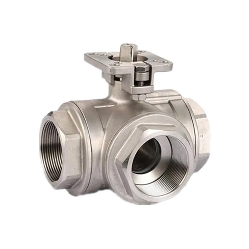
1. Why Does the Spherical Plug Sit at the Center of Every Ball Valves Design?
The spherical plug is the core of the valve. It is positioned at the intersection of the pipe bore and the valve body cavity. The plug is supported by the valve seats on both sides and by the stem at the top. The stem passes through the bonnet and connects to the handle or actuator. The plug has a machined bore, typically equal to the pipe inside diameter in a full-port design or slightly smaller in a reduced-port design. The surface of the sphere is polished to provide a smooth sealing surface against the seats. In our factory, we machine the spherical plug from stainless steel, carbon steel, or brass, depending on the application. The sphericity tolerance is held to 0.02 mm to ensure consistent contact with the seat. Wenzhou Joepai Valve Co., Ltd. has been manufacturing Ball Valves for over 15 years.
The position of the plug at the center of the body provides two benefits. The first is a straight flow path when the valve is open, which minimizes pressure drop. The second is a compact body design, because the plug rotates within the existing body cavity rather than moving along the pipe axis. This is why a ball valve requires less space than a gate valve or a globe valve of the same size.
2. How Does a Quarter-Turn of the Stem Translate Into Full Flow or Shut-Off?
The stem transmits the torque from the handle to the plug. The connection between the stem and the plug is typically a keyway, a square drive, or a pin. When the handle is turned, the stem rotates, and the plug rotates with it. The rotation is limited to 90 degrees by a stop pin or a stop plate in the bonnet. At the fully open position, the bore of the plug is aligned with the pipe bore. At the fully closed position, the bore is perpendicular to the pipe bore, and the solid sphere surface blocks the flow. The table below shows the relationship between the rotation angle and the flow characteristics.
| Rotation angle from closed | Flow area | Flow coefficient (Cv) for DN50 | Operating condition |
| 0° (fully closed) | 0% | 0 | Shut-off |
| 22.5° | 15 – 25% | 35 – 60 | Throttling (not recommended) |
| 45° | 40 – 55% | 90 – 140 | Throttling (not recommended) |
| 67.5° | 70 – 85% | 180 – 240 | Partial flow |
| 90° (fully open) | 100% | 280 – 320 | Full flow |
The flow coefficient increases rapidly as the plug approaches the fully open position. This is why ball valves are classified as on-off valves rather than control valves. The recommended practice is to use the valve in the fully open or fully closed position. In our factory, we mark the handle and the stem with the open and closed positions so that the operator can verify the valve state visually.
3. What Keeps the Ball Seated Against the Body Under Pressure and Temperature Changes?
The sealing of a Ball Valves depends on the contact between the spherical plug and the seat. There are two sealing designs: floating ball and trunnion mounted. In a floating ball design, the plug is not fixed to the stem at the bottom. The pressure of the medium pushes the plug downstream against the downstream seat, which increases the sealing force. In a trunnion mounted design, the plug is supported by bearings at the top and bottom. The seats are spring-loaded and move independently to maintain contact with the plug. The table below shows the seat materials and their operating limits.
| Seat material | Temperature range | Pressure range | Sealing characteristic |
| PTFE | -20°C to +180°C | Up to 40 bar | Excellent chemical resistance; low friction |
| RPTFE (reinforced) | -20°C to +200°C | Up to 63 bar | Better deformation resistance than PTFE |
| PEEK | -40°C to +250°C | Up to 100 bar | High temperature and pressure; moderate chemical resistance |
| Metal (Stellite) | -50°C to +500°C | Up to 250 bar | Fire-safe; not bubble-tight |
Valve engineer's note: The seat material must be selected for the operating temperature and the chemical compatibility with the medium. A PTFE seat that is suitable for water at 20°C may deform at 150°C and lose the preload. A PEEK seat is more suitable for high-temperature service but is more expensive. In our factory, we test the seat leakage of every Ball Valves at 1.1 times the rated pressure. The leakage must be zero for a soft-seated valve. Wenzhou Joepai Valve Co., Ltd. provides a seat material compatibility chart with every order.
4. Why Does the Stem Seal and Bearing Design Determine How Smoothly the Ball Rotates?
The stem seal prevents the medium from leaking to the atmosphere along the stem. The bearing supports the stem and reduces the friction during rotation. The most common stem seal is an O-ring or a set of PTFE chevron packing. The most common bearing is a PTFE-lined sleeve or a bronze bushing. The rotation torque depends on the friction in the stem seal, the friction between the plug and the seat, and the friction in the bearing. A poorly designed stem seal can increase the torque by 50 percent or more. The table below shows the typical torque values for different valve sizes and seat materials.
| Valve size (DN) | PTFE seat torque (Nm) | PEEK seat torque (Nm) | Metal seat torque (Nm) |
| 25 | 8 – 12 | 10 – 15 | 15 – 22 |
| 50 | 25 – 35 | 30 – 45 | 45 – 65 |
| 80 | 55 – 75 | 70 – 95 | 95 – 130 |
| 100 | 90 – 120 | 110 – 150 | 150 – 200 |
| 150 | 200 – 260 | 250 – 330 | 330 – 450 |
In our factory, we measure the rotation torque of every Ball Valves after assembly. The torque must be within the specification for the valve size and seat material. We also perform a cycle test of 1,000 open-close operations to verify that the torque does not increase significantly over time. Joepai provides a torque test report with each shipment.
5. How Should Engineers Verify Rotation, Sealing, and Torque Before Commissioning a Ball Valves?
Before commissioning, the engineer should perform four checks. The first is the rotation check. The handle should turn smoothly from the fully open to the fully closed position without binding. The open and closed position indicators should align with the actual valve state. The second is the shell test. The valve body is pressurized with water or air at 1.5 times the rated pressure, and the body is checked for leakage. The third is the seat test. The valve is closed, and the upstream side is pressurized at 1.1 times the rated pressure. The downstream side is checked for leakage. The fourth is the torque check. The measured torque should be compared with the specification. In our factory, we perform these checks on every valve before shipment. We also recommend that the installer repeat the rotation check after the valve is installed in the line, because the pipe alignment and the flange bolting can affect the rotation.
The most common installation error is over-tightening the flange bolts. Over-tightening can distort the valve body and increase the rotation torque. The second most common error is welding the valve into the line without removing the handle or protecting the seat from heat. The welding heat can damage the PTFE seat. Wenzhou Joepai Valve Co., Ltd. provides an installation guide that covers the correct bolt torque and the welding protection procedure.
Frequently Asked Questions About Ball Valve Rotation and Sealing
Summary for Valve Engineers and Maintenance Technicians
The spherical plug in a Ball Valves rotates through 90 degrees to align or block the flow path. The rotation is transmitted from the handle through the stem to the plug. The sealing is maintained by the contact between the plug and the seat, with the seat material selected for the temperature and the medium. The stem seal and the bearing determine the rotation torque. The verification before commissioning includes the rotation check, the shell test, the seat test, and the torque check. By understanding the rotation mechanism and the sealing principles, engineers can specify, install, and maintain ball valves that operate reliably for the life of the system. Wenzhou Joepai Valve Co., Ltd. has been manufacturing Ball Valves for over 15 years and provides full technical support for our customers.