

How Does a Control Valve Act as the Final Control Element in Automation Loops?
2026-09-02
In any automated process control system, the final control element is the device that physically adjusts the manipulated variable to bring the process back to setpoint. Among all final control elements—pumps, heaters, variable speed drives—the control valve is the most common and the most critical. Its performance directly determines whether a PID loop can maintain stable control. This article provides a complete technical reference for engineers, covering the valve's role in the loop, the factors that affect its response, and the data needed for proper selection and tuning.
1. What Is the Role of the Control Valve in a Process Automation Loop?
A process automation loop consists of four basic elements: a sensor that measures the process variable, a controller that compares the measured value to the setpoint, a final control element that adjusts the process input, and the process itself. The control valve is the final control element in the majority of fluid process loops. It receives a signal from the controller—typically 4 to 20 mA or a digital fieldbus command—and converts that signal into a mechanical position that changes the flow rate. This flow rate change then affects the process variable. In this sequence, the valve is the only component that physically interacts with the process material. Its speed, accuracy, and repeatability limit the overall performance of the loop. A slow or sticky valve will cause the controller to overshoot or oscillate, regardless of how well the PID gains are tuned. In our factory, we manufacture Conventional Series Control Valve units with a positioner response time of under 200 milliseconds to ensure that the valve does not become the bottleneck in the loop.
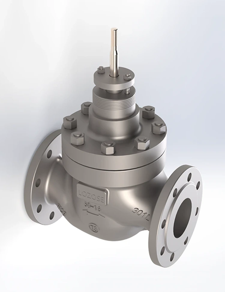
The valve's role extends beyond simple positioning. It must also maintain a stable flow characteristic across its operating range, handle the process pressure and temperature, and provide tight shutoff when required. Zhejiang Lozose Intelligent Control Instrument Co., Ltd. designs its Conventional Series Control Valve with these requirements in mind, offering multiple trim options to match the specific process conditions.
2. How Does the Valve's Inherent Flow Characteristic Affect Loop Gain?
The inherent flow characteristic of a control valve defines the relationship between the valve stem position and the flow rate under a constant pressure drop. This characteristic determines how the loop gain changes as the valve moves through its travel range. There are three standard characteristics used in industrial control. The linear characteristic provides a constant relationship between valve position and flow—a 10 percent change in position produces a 10 percent change in flow. This is suitable for loops where the pressure drop across the valve is constant. The equal percentage characteristic provides a constant percentage change in flow for a given change in position—a 10 percent change in position produces a 10 percent increase in the current flow rate. This compensates for decreasing pressure drops in systems where the valve is sized for a wide flow range. The quick opening characteristic provides a large flow change at the initial opening, which is typically used for on-off applications. The table below summarizes the application and loop gain implications of each characteristic.
| Inherent characteristic | Flow change per 10% stem travel | Typical application | Loop gain stability |
| Linear | Constant (10% of maximum flow) | Liquid level, constant pressure drop systems | Gain is constant across operating range |
| Equal percentage | Increases with travel (compounded) | Pressure control, varying pressure drop systems | Gain increases with flow, compensates for system gain decrease |
| Quick opening | High at low travel, then low | On-off control, bypass, emergency shutdown | Not suitable for continuous control |
Selecting the wrong characteristic is a common cause of poor loop performance. If an equal percentage valve is used in a system with a constant pressure drop, the loop gain will increase at high flow rates, causing instability at high loads. Conversely, a linear valve in a variable pressure drop system will have low gain at high flow, causing sluggish response. At Lozose, we recommend performing a process gain analysis before selecting the valve characteristic. Our Conventional Series Control Valve units are available with interchangeable trim sets, allowing the characteristic to be changed in the field without replacing the entire valve body.
3. What Valve Response Parameters Determine Loop Stability?
Three valve response parameters directly affect loop stability: deadband, stroking speed, and repeatability. Deadband is the range of input signal change that produces no valve movement. It is caused by friction in the packing and the stem seal, and by mechanical play in the linkage. Stiction is a related phenomenon where the valve sticks in position and then jumps when the signal overcomes the friction. Both deadband and stiction introduce a non linearity in the loop that can cause limit cycling. Stroking speed determines how fast the valve can respond to a setpoint or disturbance change. If the stroking speed is too slow, the controller will need to be detuned to prevent overshoot. Repeatability is the ability of the valve to return to the same position for a given input signal. Poor repeatability introduces a time varying gain that makes loop tuning unreliable. In our factory, we test every Conventional Series Control Valve for deadband, stroking speed, and repeatability at the factory. The test data is provided with each valve, allowing the commissioning engineer to validate the field performance against the factory baseline.
Technical note: The valve stroking speed should be matched to the process time constant. For fast loops with a time constant under 1 second, a pneumatic valve with a high flow positioner is required. For slow temperature loops with a time constant over 60 seconds, the stroking speed is less critical. Our factory provides a valve sizing and response calculation tool that recommends the optimal stroking speed for your process dynamics.
4. How Does the Valve Positioner Improve Control Accuracy?
The valve positioner is the device that receives the controller output signal and converts it into a pneumatic or electric signal that drives the actuator. A positioner performs three critical functions: it amplifies the signal to overcome friction, it provides position feedback for closed loop positioning, and it allows the valve characteristic to be modified through cams or digital programming. A valve without a positioner will have a larger deadband and slower response because the actuator must overcome the friction directly. A positioner equipped Conventional Series Control Valve can reduce deadband to below 0.5 percent of span. Digital positioners go further by providing diagnostics, including the ability to perform signature tests and trend analysis. These diagnostics allow predictive maintenance, identifying wear in the packing, the seat, or the actuator diaphragm before a failure occurs. In our factory, we equip all Conventional Series Control Valve units with a digital positioner as a standard option. The positioner stores the valve signature from the factory test, which can be compared to field data to detect changes in friction or seating force.
Frequently Asked Questions About Control Valves in Automation Loops
Control Valve Performance: Key Takeaways for Process Engineers
The control valve is the final control element in the automation loop, and its performance sets the upper limit on the loop's overall stability and responsiveness. The factors that matter most are the inherent flow characteristic, the deadband and stroking speed, the positioner accuracy, and the proper installation practices. By selecting the correct valve characteristic, verifying the valve response parameters, and performing regular diagnostics, engineers can ensure that the valve does not become the weakest link in the loop. Zhejiang Lozose Intelligent Control Instrument Co., Ltd. manufactures Conventional Series Control Valve units that are designed for reliable performance in a wide range of process applications. Each valve is tested and documented, providing the data needed for confident engineering decisions.