

How Do Post-Processing Methods Affect the Fatigue Life of High-Strength Metal 3D Printed Parts
2026-07-24
When engineering teams evaluate High-Strength Metal 3D Printed Parts for mission-critical applications, the conversation rarely stops at tensile strength or hardness. The real differentiator between a prototype and a production-ready component often lies in fatigue performance—and that is where post-processing becomes the decisive factor. At Honmor, we have observed that identical as-printed specimens can exhibit fatigue life variations exceeding 500% solely based on the chosen post-treatment pathway. This blog breaks down the scientific and practical relationships between common post-processing techniques and the cyclic durability of High-Strength Metal 3D Printed Parts, offering data-driven guidance for engineers and procurement specialists.
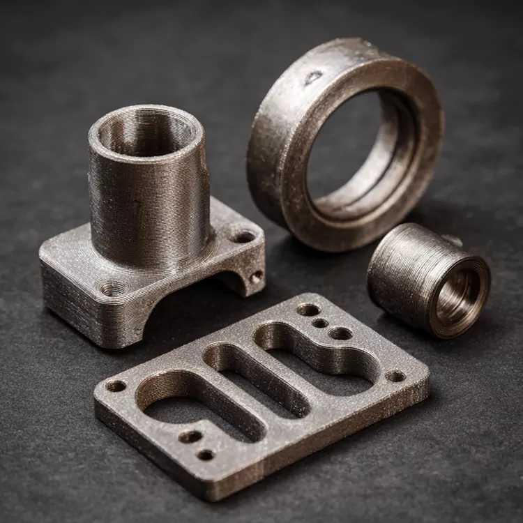
The Root Cause: Why As-Printed Parts Underperform Under Cyclic Loading
Before examining solutions, it is essential to understand the problem. High-Strength Metal 3D Printed Parts produced via Laser Powder Bed Fusion (LPBF) or Electron Beam Melting (EBM) possess three intrinsic fatigue limiters:
-
Surface roughness (Ra typically 6–15 µm) creates stress concentration sites.
-
Tensile residual stresses from rapid thermal cycling promote early crack initiation.
-
Subsurface porosity (0.1–1.5% by volume) acts as internal notch multipliers.
Post-processing directly addresses each of these factors, but not all methods deliver equal benefits—and some can even degrade fatigue life if improperly applied.
Comparative Table: Post-Processing Methods vs. Fatigue Performance
| Post-Processing Method | Primary Effect | Fatigue Life Change (vs. As-Printed) | Best Suited For |
|---|---|---|---|
| Stress Relief Annealing | Reduces residual stresses by 60–80% | +30% to +50% | Geometrically complex thin sections |
| Hot Isostatic Pressing (HIP) | Closes internal pores + homogenizes microstructure | +80% to +150% | Aerospace & pressure-retaining parts |
| CNC Machining (finish pass) | Removes surface asperities (Ra < 1.6 µm) | +100% to +200% | Bearing surfaces and sealing interfaces |
| Shot Peening | Induces compressive residual stress layer | +120% to +250% | High-cycle fatigue applications ( >10⁶ cycles) |
| Chemical Polishing | Smooths re-entrant features without mechanical force | +40% to +70% | Internal channels and lattice structures |
| Heat Treatment + Aging | Precipitates strengthening phases (e.g., γ' in Inconel) | +50% to +90% | Nickel-based superalloys and tool steels |
| Combined HIP + Machining + Peening | Addresses bulk, surface, and subsurface simultaneously | +200% to +350% | Ultimate-performance components |
Mechanistic Insights: Why Surface and Subsurface Both Matter
Fatigue failure in High-Strength Metal 3D Printed Parts typically initiates at the surface in low-cycle fatigue (LCF) regimes, but transitions to subsurface pore-driven initiation in high-cycle fatigue (HCF) regimes above 10⁷ cycles. This bifurcation means that surface-only treatments (like machining or polishing) deliver diminishing returns if porosity remains unresolved.
Honmor recommends a tiered strategy:
-
For LCF (<10⁵ cycles): Prioritize surface finishing + shot peening. The compressive layer retards crack propagation more effectively than porosity closure.
-
For HCF (>10⁷ cycles): Mandate HIP as the foundational step, followed by at least one surface refinement process.
-
For thermal-mechanical fatigue: Combine HIP with a sub-solvus anneal to stabilize grain structure against cyclic softening.
Industry Data Snapshot (LPBF Ti-6Al-4V)
A representative example from Honmor’s internal validation database (tested at R=0.1, 20 Hz, room temperature):
| Condition | Fatigue Strength @ 10⁷ cycles (MPa) | Improvement over As-Printed |
|---|---|---|
| As-printed (no treatment) | 280 | Baseline |
| Stress relief only | 370 | +32% |
| HIP only | 460 | +64% |
| Machined (surface Ra 1.2 µm) | 510 | +82% |
| HIP + Machined | 590 | +111% |
| HIP + Machined + Shot Peened | 680 | +143% |
These figures underscore that the synergistic combination of bulk densification and surface engineering consistently outperforms any single-step remedy. Honmor integrates this multi-stage logic into our standard production workflow for aviation and motorsport clients.
Frequently Asked Questions (FAQ) About High-Strength Metal 3D Printed Parts
Q1: Can post-processing completely eliminate the fatigue anisotropy in High-Strength Metal 3D Printed Parts?
A1: Not completely, but it can significantly reduce it. Fatigue anisotropy in LPBF parts arises from columnar grain structures and elongated pores aligned with the build direction. HIP treatment closes most elongated pores and promotes recrystallization, which reduces the fatigue strength difference between horizontal and vertical orientations from approximately 40% (as-printed) to under 15% after HIP + full heat treatment. However, complete isotropy remains unattainable because the original grain morphology leaves a "texture memory" even after thermal exposure. For applications requiring near-isotropic performance, Honmor recommends designing the build orientation to place the highest cyclic loads perpendicular to the build layers, then applying HIP + a secondary solution anneal above the β-transus for titanium alloys. This approach delivers the most balanced fatigue response across all load directions.
Q2: Which post-processing method offers the best cost-to-fatigue-life improvement ratio for High-Strength Metal 3D Printed Parts in small-batch production?
A2: For batch sizes under 100 units, CNC machining of critical surfaces only combined with a standard stress-relief anneal offers the highest ROI. This pair costs roughly 15–20% of the as-printed part value but delivers 80–100% fatigue life extension—sufficient for most industrial machinery and tooling applications. Full HIP becomes cost-effective only when the part value exceeds $500 per kilogram or when the application demands >10⁷ cycle reliability. Honmor often advises clients to perform a cost-per-cycle calculation: divide the post-processing expense by the projected fatigue life gain. In our experience, targeted machining outperforms blanket HIP for parts with simple geometries, while complex internal-featured parts force the opposite conclusion. We also offer a tiered post-processing menu so customers can match treatment intensity to actual duty cycles rather than over-engineering.
Q3: How does shot peening affect the high-temperature fatigue life of High-Strength Metal 3D Printed Parts made from Inconel 718?
A3: Shot peening introduces a compressive residual stress layer that remains effective up to approximately 450°C for Inconel 718. Above that temperature, thermal relaxation reduces the compressive magnitude by 50–60% within the first 100 hours of exposure, eroding most of the HCF benefit. However, peening still provides a secondary advantage: it refines the surface grain structure through severe plastic deformation, which slows oxidation-assisted crack initiation even at 650°C. For sustained high-temperature operation (>600°C), Honmor recommends substituting shot peening with a low-plasticity burnishing (LPB) process, which produces deeper compressive layers (up to 300 µm) that resist thermal decay more effectively. Alternatively, a post-peening stabilization heat treatment at 520°C for 4 hours can lock in the compressive field with only 10–15% relaxation. Always validate with coupon testing at your actual service temperature, as alloy batch and build parameters shift the relaxation kinetics noticeably.
Practical Decision Matrix for Engineers
| If your primary concern is... | Choose this post-processing sequence | Avoid |
|---|---|---|
| Surface-initiated cracking under vibration | Machining + Shot Peening | Chemical polishing alone |
| Internal porosity from thick-section builds | HIP + Slow-cool furnace anneal | Fast-cool stress relief |
| Dimensional tolerance + fatigue | Rough machining → HIP → Finish machining | Finish machining before HIP |
| Corrosive + cyclic environment | HIP + Electropolishing + Passivation | Shot peening (may embed contaminants) |
| Budget-constrained prototyping | Stress relief + Critical-surface sanding | Full HIP or multi-step treatments |
Final Recommendations from Honmor
No single post-processing recipe fits every geometry, alloy, or duty profile. The optimal pathway depends on:
-
Build orientation and support structure design
-
Target fatigue regime (LCF vs. HCF)
-
Service temperature and environment
-
Acceptable cost premium per part
Honmor employs a fatigue-focused quality gate: every batch of High-Strength Metal 3D Printed Parts destined for cyclic-load applications undergoes either rotating-beam fatigue testing or ultrasonic resonance testing to validate the selected post-processing efficacy. We also maintain a proprietary process-property database that links specific LPBF parameter sets to post-treatment outcomes—allowing us to predict fatigue performance within ±8% without destructive testing.
Contact Us
Fatigue performance is not a guessing game—it is an engineering decision supported by data, experience, and rigorous testing. If you are currently specifying or sourcing High-Strength Metal 3D Printed Parts for applications where cyclic reliability matters, Honmor is ready to assist. Our team offers free preliminary process consultations, benchmark sample production, and full post-processing validation reports. Reach out to our engineering department through the contact form on our website or email us directly to discuss your specific load cases, materials, and production volumes. Let us help you turn additive manufacturing into a dependable, fatigue-validated solution—not just a rapid prototype. Contact Honmor today and move from uncertainty to certified performance.