

How Do Gate Valves Control Flow in Industrial Piping Systems?
2025-12-25
Abstract
Gate valves are widely deployed in industrial piping systems where full-flow isolation and minimal pressure loss are required. This article provides a comprehensive technical explanation of how gate valves operate, where they are applied, and how they are specified for different industries. The discussion focuses on structural design, operational mechanisms, material selection, dimensional standards, and long-term system compatibility. Common technical questions are addressed to support informed procurement and engineering decisions while aligning with international standards and search behavior.
Outline
- Product Overview and Core Purpose
- Technical Parameters and Structural Design
- Operational Principles and Application Scenarios
- Selection Logic, Industry FAQs, and Lifecycle Considerations
Table of Contents
- 1. What Defines a Gate Valve in Industrial Systems?
- 2. How Are Gate Valves Engineered and Specified?
- 3. How Do Gate Valves Perform Across Applications?
- 4. How Should Gate Valves Be Selected and Maintained?
1. What Defines a Gate Valve in Industrial Systems?
A gate valve is a linear-motion isolation valve designed to start or stop fluid flow by raising or lowering a flat or wedge-shaped gate within the valve body. Unlike throttling valves, gate valves are intended for fully open or fully closed positions, ensuring unobstructed flow paths and reduced turbulence.
In pipeline systems, gate valves are commonly positioned where flow interruption is infrequent but absolute shutoff reliability is required. When fully open, the gate retracts completely from the flow path, allowing the medium to pass with minimal resistance. This design characteristic makes gate valves suitable for high-pressure and large-diameter applications.
The central objective of this article is to clarify how gate valves function from a mechanical and system-integration perspective, while outlining the parameters that determine their suitability across industries such as oil and gas, water treatment, power generation, and chemical processing.
2. How Are Gate Valves Engineered and Specified?
Gate valve engineering is driven by pressure ratings, temperature tolerance, media compatibility, and installation orientation. The internal gate may be solid wedge, flexible wedge, split wedge, or parallel slide, each configuration addressing different thermal and sealing requirements.
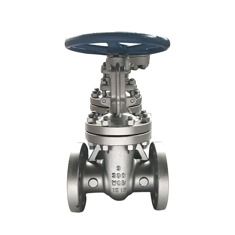
Key Structural Components
A standard gate valve assembly consists of a valve body, bonnet, gate, stem, seat rings, packing, and actuator interface. Material selection for each component directly impacts corrosion resistance, mechanical strength, and service life.
Typical Technical Parameters
| Parameter | Specification Range |
|---|---|
| Nominal Diameter (DN) | DN50 – DN1200 |
| Pressure Rating | PN10 – PN420 / Class 150 – Class 2500 |
| Body Materials | Cast Iron, Carbon Steel, Stainless Steel, Alloy Steel |
| Connection Type | Flanged, Butt Weld, Socket Weld |
| Operating Method | Manual, Gear Operated, Electric, Pneumatic |
Dimensional standards typically comply with ANSI, ASME, API, DIN, or ISO requirements, ensuring compatibility with global piping networks. Stem design may be rising or non-rising, influencing installation space and visual position indication.
3. How Do Gate Valves Perform Across Applications?
Gate valves are applied in systems where fluid flow must be completely isolated for maintenance, safety, or operational control. Their straight-through flow path reduces energy loss and prevents sediment accumulation when fully open.
Industry Application Examples
In water distribution networks, gate valves are installed at sectional control points to isolate pipeline segments. In oil and gas transmission, high-pressure gate valves manage upstream and downstream shutoff under extreme operating conditions. Chemical processing facilities rely on material-specific gate valves to handle corrosive or high-temperature media.
Operational performance depends on correct installation, including alignment, torque calibration, and proper packing compression. Gate valves are not recommended for flow modulation, as partial opening can cause vibration, erosion, and premature seat damage.
4. How Should Gate Valves Be Selected and Maintained?
Gate valve selection requires alignment between system design conditions and valve specifications. Media characteristics, pressure cycles, temperature fluctuations, and actuation frequency must be evaluated before procurement.
Common Gate Valve Questions and Answers
Q: How does a gate valve differ from a ball valve?
A: A gate valve uses a linear-moving gate to isolate flow and is suited for infrequent operation, while a ball valve rotates a spherical closure and supports faster on-off cycles.
Q: Can gate valves be installed in vertical pipelines?
A: Gate valves can be installed vertically, provided stem orientation and actuator support are correctly configured to avoid uneven gate loading.
Q: Why is a gate valve leaking when fully closed?
A: Leakage may result from seat wear, debris accumulation, thermal distortion, or insufficient closing torque, requiring inspection and possible seat refurbishment.
Maintenance and Lifecycle Considerations
Routine inspection focuses on stem lubrication, packing condition, and actuator responsiveness. During extended shutdowns, cycling the valve periodically helps prevent seizing and surface adhesion.
Proper documentation of operating parameters and maintenance history contributes to predictable service life and system reliability.
Conclusion and Industry Perspective
Gate valves remain a foundational component in industrial flow control systems due to their straightforward design and compatibility with high-capacity pipelines. Understanding their engineering logic and application boundaries supports better system planning and long-term operational stability.
As a supplier committed to industrial valve solutions, Hanno provides gate valves engineered to meet international standards and diverse application requirements. For detailed specifications, project consultation, or customized solutions, contact the technical team to discuss system-specific needs.
Contact us today to obtain professional guidance and reliable gate valve solutions for industrial projects.