

How Do Butterfly Valves Ensure Reliable Operation in High-Head Hydropower Systems?
2026-09-17
1. Why Is the Butterfly Valve Preferred Over Other Valve Types in High-Head Hydropower?
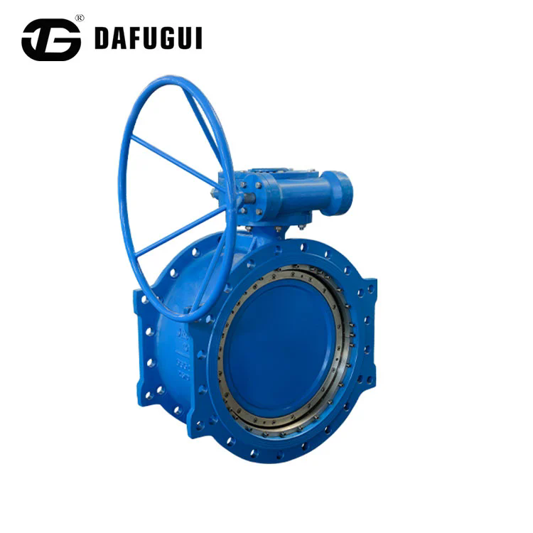
There are three main valve types used in hydropower inlet applications: the Butterfly Valve, the spherical valve, and the gate valve. Each has advantages and limitations. The spherical valve provides a bubble-tight seal and low operating torque, but it is large, heavy, and expensive. The gate valve is simple and robust, but it requires a tall structure and has a slow closing time. The Butterfly Valve offers a balance of compactness, speed, and cost. A Butterfly Valve with a diameter of 2 meters can be installed in a space that would require a gate valve of 4 meters height. The Butterfly Valve can close in 30 to 60 seconds, which is fast enough to protect the turbine from overspeed. And the cost of a Butterfly Valve is typically 40 to 60 percent lower than a spherical valve of the same diameter. In our factory, we manufacture Butterfly Valve units specifically for hydropower applications, with pressure ratings up to PN40 and diameters up to 3,000 mm.
High-head challenge: At a head of 300 meters, the water pressure at the valve inlet is approximately 30 bar. The valve disc must withstand this pressure without excessive deflection, and the seal must maintain contact without being extruded or damaged.
Dafugui Pipe Valve Co., Ltd. has been supplying Butterfly Valve units to hydropower projects for over 20 years. Our valves are installed in stations with heads ranging from 50 meters to 600 meters. The design of the valve body, disc, and seal is optimized for each project based on the specific head and flow conditions.
2. What Are the Primary Failure Modes for Butterfly Valves in High-Head Service?
There are four primary failure modes for a Butterfly Valve in high-head hydropower service. The first is seal extrusion. The seal is typically made from rubber or PTFE. Under high pressure, the seal can be extruded into the clearance between the disc and the valve body, causing damage and leakage. The second is disc deflection. The disc is subjected to bending stress from the water pressure. If the deflection is excessive, the seal will not contact the seat uniformly, and leakage will occur. The third is cavitation erosion. When the valve is partially open, the high-velocity water can create cavitation bubbles that collapse and erode the disc and the valve body. The fourth is bearing wear. The shaft bearings must support the weight of the disc and the thrust from the water pressure. If the bearings wear, the disc alignment changes, and the seal fails. The table below summarizes these failure modes and the design features that prevent them.
| Failure mode | Root cause | Preventive design feature | Verification method |
| Seal extrusion | High pressure, large clearance | Anti-extrusion ring, tight tolerance | Pressure test at 1.5x rated |
| Disc deflection | Bending stress from pressure | Ribbed disc, FEA optimization | Strain gauge test |
| Cavitation erosion | High velocity at partial opening | Streamlined disc profile, hard facing | CFD analysis, cavitation test |
| Bearing wear | Thrust load, inadequate lubrication | Self-lubricating bearings, sealed housing | Cycle test, wear measurement |
Our factory uses finite element analysis to optimize the disc profile for each valve size and pressure rating. The analysis predicts the maximum deflection at the center of the disc under the design pressure. We also use computational fluid dynamics to simulate the flow pattern at different opening angles and to identify areas where cavitation is likely to occur.
3. What Seal Designs Are Used to Achieve Reliable Sealing in High-Head Butterfly Valves?
The seal is the most critical component of a Butterfly Valve in high-head service. There are three main seal designs: the resilient seat, the metal seat, and the double-offset seat. The resilient seat uses a rubber or PTFE seal that is compressed against the metal disc. It provides a bubble-tight seal but is limited in temperature and pressure. The metal seat uses a metal-to-metal contact between the disc and the seat. It is suitable for high temperatures but does not provide a bubble-tight seal. The double-offset seat is a hybrid design that uses a resilient seal but with an offset geometry that reduces friction and wear. The table below compares the performance of these seal designs.
| Seal design | Maximum pressure (bar) | Maximum temperature (°C) | Leakage rate | Typical application |
| Resilient seat (rubber) | 16 | 80 | Bubble-tight | Low to medium head |
| Resilient seat (PTFE) | 25 | 200 | Bubble-tight | Medium head, chemical |
| Metal seat | 40 | 400 | Class IV | High head, high temperature |
| Double-offset with PTFE | 40 | 200 | Bubble-tight | High head, frequent operation |
For high-head hydropower applications, we recommend the double-offset design with a PTFE seal. The offset geometry reduces the friction between the seal and the seat during opening and closing, which extends the seal life. The PTFE seal provides a bubble-tight seal at pressures up to 40 bar. In our factory, we test every Butterfly Valve with a hydrostatic pressure test at 1.5 times the rated pressure and a leakage test with air or water.
4. How Is the Operating Torque Managed in High-Head Butterfly Valves?
The operating torque of a Butterfly Valve is determined by three factors: the bearing friction, the seal friction, and the hydrodynamic torque from the water flow. In high-head applications, the hydrodynamic torque can be significant, especially when the valve is partially open. The actuator must be sized to provide enough torque to open and close the valve under the worst-case conditions. If the actuator is undersized, the valve may not close fully, which can lead to turbine damage. In our factory, we calculate the operating torque for each valve based on the flow conditions, the pressure drop, and the seal design. We then select an actuator with a safety factor of at least 1.5. The table below shows the typical operating torque for different valve sizes at a pressure of 30 bar.
| Valve size (mm) | Bearing friction torque (Nm) | Seal friction torque (Nm) | Hydrodynamic torque (Nm) | Total torque (Nm) |
| 600 | 120 | 180 | 350 | 650 |
| 1000 | 280 | 420 | 950 | 1,650 |
| 1600 | 650 | 980 | 2,400 | 4,030 |
| 2200 | 1,200 | 1,800 | 4,800 | 7,800 |
The hydrodynamic torque is the largest component at partial opening. For this reason, we recommend that the valve be operated either fully open or fully closed, and that the transition through the partial opening range be as quick as possible. Our Butterfly Valve units are equipped with actuators that provide the required torque and speed for reliable operation.
Frequently Asked Questions About Butterfly Valves in High-Head Hydropower Systems
Summary for Hydropower Engineers
Butterfly Valves are the preferred choice for high-head hydropower inlet applications because they combine compactness, speed, and cost-effectiveness. The reliability of the valve depends on the seal design, the disc stiffness, the cavitation resistance, and the bearing system. The double-offset design with a PTFE seal provides the best combination of sealing performance and operating life. The actuator must be sized with an adequate safety factor to handle the hydrodynamic torque. Dafugui Pipe Valve Co., Ltd. has been supplying Butterfly Valve units to hydropower projects for over 20 years and provides full engineering support for valve selection and maintenance.
Dafugui Pipe Valve Co., Ltd. manufactures Butterfly Valve units for hydropower applications with pressure ratings up to PN40 and diameters up to 3,000 mm. We provide FEA analysis, CFD simulation, and factory testing for all of our valves.